RIS components
June 22, 2021 · View on GitHub
This is a python project for RIS(reconfigurable intelligent surface) simulations.
related works
- My first paper Link to my paper / Pdf to my paper:
[1] X. Guo, Y. Chen and Y. Wang, "Learning-based Robust and Secure Transmission for Reconfigurable Intelligent Surface Aided Millimeter Wave UAV Communications," in IEEE Wireless Communications Letters, doi: 10.1109/LWC.2021.3081464.
- DDPG structure
Refer to the following code on github:
a. tf-agent this is the easiest way the use the official RL(reinforcement learning) api.
b. open source RL api using tensorflow: (coming soon) c. DDPG structure refters to [3](pdf). There has already been some works on the combination of the DDPG and the RIS [4](pdf)
- RIS simulation Refer to the paper Link to this paper / Pdf to this paper. This paper provide a simulation code in matlab, we refer to this project to provide a python version.
[2] E. Basar and I. Yildirim, "SimRIS Channel Simulator for Reconfigurable Intelligent Surface-Empowered Communication Systems," 2020 IEEE Latin-American Conference on Communications (LATINCOM), 2020, pp. 1-6, doi: 10.1109/LATINCOM50620.2020.9282349.
What this project aims ?
This project aims to redo the simulations shown in the paper below Link to this paper:
[3] Zhang, Zijian, et al. "Active RIS vs. Passive RIS: Which Will Prevail in 6G?." arXiv preprint arXiv:2103.15154 (2021).
Specifically, in this project we will simulate the active RIS. And to maximum the universality, this project will provide modular simulation tool for RIS-aided system.
File structure
./cite
The cited paper for this project
./learning
The code to initialize the agents
./learning/official
The offical RL agents api (tf-agent)
./learning/custom
The third party open source RL agent api
RIS theory
this section mainly refers to [2] (SimRIS1.0) and [2.2] (SimRIS2.0).
RIS-Assisted LOS channels(SISO)
According to the plate scattering theory[2,(1)], the transmitted signal is captured by each RIS element, then rescattered to the medium in all directions. Focusing on he -th RIS element, the captured power on it can be readily obtained as
where is the transmit power, is the transmit antenna gain in the direction of the -th RIS element (or the RIS in general), is the gain of the corresponding RIS element in the direction of the transmitter (Tx), is the wavelength, and is the distance between the transmitter and this element. The effective aperture of the -th RIS element is , and the power flux density incident on it given by . Then the captured power is re-radiated to the medium with an efficiency factor , which in [2] is assumed to be unity.
The captured power at the receiver (Rx) is obtained as
where is the receive antenna gain in the direction of the -th RIS element and is the gain of the corresponding RIS element in the direction of the receiver. For the same scenario, let us consider the radar range equation given by
where is the radar cross section (RCS, in ) of the RIS element with being its physical area. (2) and (3) are actually the same, given .
Let's assum the parameters as:
| Parameter |
|---|
| (Reference)[2-9] |
Then the received power through -th RIS element is:
The total path loss is:
In general, the received signal at the receiver is:
Where and respectively stand for controllable magnitude and phase response of the nth element, is the wave number, and is the transmitted signal. . One can easily observe from (6) that the received signal power can be maximized by adjusting RIS element phases as . Finally, it is worth noting that the direct link between Tx and Rx can be incorporated into the model by
Where and being the Tx-Rx distance.
RIS-Assisted channels(MIMO)[2.2]
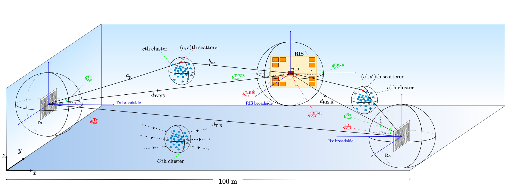
| Parameter | Meanings | Dimension |
|---|---|---|
| transmiter antennas number | ||
| receiver antennas number | ||
| End-to-end channel matrix | ||
| Direct channel matrix | ||
| The matrix of channel coefficients between the Tx and the RIS | ||
| The matrix of channel coefficients between the Tx and the RIS | ||
| The response of the RIS array |
channel generation
The detailed channel modeling can be seen in 3GPP 38.901 [5].
The basic idea to model the mmWave channel is to consider the channel under SISO senirio and then by multiplexing the array response, we can get the result of a mmWave channel under MIMO senirio.
The detailed SISO channel model can be found in [6]
path loss
cluster and sub-ray
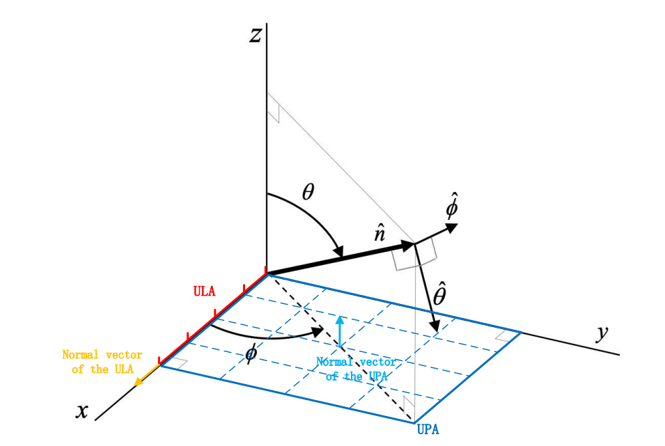
array response
the defination of the AoA and AoD is shown below:
Others
coding platform: Win10 pro, anaconda3
nvidia driver: 466.47
cuda version: cuda_11.1.1_456.81_win10
cuddn version: cudnn-11.2-windows-x64-v8.1.1.33
tensorflow version: 2.4.0
python version: 3.8.10
Cited papers
[1](pdf) X. Guo, Y. Chen and Y. Wang, "Learning-based Robust and Secure Transmission for Reconfigurable Intelligent Surface Aided Millimeter Wave UAV Communications," in IEEE Wireless Communications Letters, doi: 10.1109/LWC.2021.3081464.
[2.0] E. Basar and I. Yildirim, "SimRIS Channel Simulator for Reconfigurable Intelligent Surface-Empowered Communication Systems," 2020 IEEE Latin-American Conference on Communications (LATINCOM), 2020, pp. 1-6, doi: 10.1109/LATINCOM50620.2020.9282349. note this and [2.1] is corresponding to the SimRIS1.0 which considers the SISO system
[2.1] E. Basar, I. Yildirim, “Indoor and Outdoor Physical Channel Modeling and Efficient Positioning for Reconfigurable Intelligent Surfaces in mmWave Bands“, ArXiv:2006.02240, May 2020
[2.2] E. Basar, I. Yildirim, “SimRIS Channel Simulator for Reconfigurable Intelligent Surfaces in Future Wireless Networks”, ArXiv:2008.01448, Aug. 2020.this is corresponding to the SimRIS2.0 which considers the MIMO system
[3](pdf) Lillicrap, Timothy P., et al. "Continuous control with deep reinforcement learning." arXiv preprint arXiv:1509.02971 (2015).
[4](pdf) Wang, Liang, et al. "Joint trajectory and passive beamforming design for intelligent reflecting surface-aided UAV communications: A deep reinforcement learning approach." arXiv preprint arXiv:2007.08380 (2020).
[5] 3GPP, “Study on channel model for frequencies from 0.5 to 100 GHz,” 3rd Generation Partnership Project (3GPP), Technical Specification (TS) 38.901, 01 2020, version 16.1.0. [6] E. Basar and I. Yildirim, “Indoor and outdoor physical channel modeling and efficient positioning for reconfigurable intelligent surfaces in mmWave bands,” Aug. 2020. [Online]. Available: https://arxiv.org/abs/2006.02240