ATtiny1634
August 16, 2023 · View on GitHub

| Specification | ATtiny1634 | ATtiny1634 | ATtiny1634 |
|---|---|---|---|
| Bootloader (if any) | None | Optiboot | Micronucleus |
| Uploading uses | ISP/SPI pins | Serial Adapter | USB (directly) |
| Flash available | 16384 bytes | 15744 bytes | TBD bytes |
| RAM | 1024 bytes | 128 bytes | 128 bytes |
| EEPROM | 256 bytes | 64 bytes | 64 bytes |
| GPIO Pins | 17 + RESET | 17 + RESET | 17 + RESET |
| ADC Channels | 12 | None | None |
| PWM Channels | 4 | 4 | 4 |
| Interfaces | USI, 2xUSART | USI, USART | USI, USART |
| Interfaces | I2C slave | USI, USART | USI, USART |
| Clocking Options | in MHz | in MHz | in MHz |
| Int. Oscillator | 8, 4, 2, 1 | 8, 4, 2, 1 | 8, 4, 2, 1 |
| Int. ULP Oscillator | 128 kHz | 128 kHz | 128 kHz |
| Internal, with tuning | 8, 12, 12.8 | 8, 12, 12.8 | 8, 12, 12.8 |
| External Crystal | Up to 16 MHz | Up to 16 MHz | Up to 16 MHz |
| External Clock | Up to 16 MHz | Up to 16 MHz | Up to 16 MHz |
| LED_BUILTIN | PIN_PC0 | PIN_PC0 | PIN_PC2 |
Overview
Unlike most classic ATtiny parts, the 1634 is only spec'ed for maximum clock speed of 12 MHz. However experience has shown that it generally works at 16 MHz @ 5V. The ATtiny1634R has a more tightly factory calibrated internal oscillator. It is otherwise identical, has the same signature, and is interchangible.
This is one of the last three classic tinyAVRs to be released, and you can see that they were playing around with things a bit, not always successfully.
Warning: PB3 does not work as an input unless watchdog timer is running
This is a design flaw in the chip, as noted in the datasheet errata. Additionally, when the "ULP" oscillator (used by the WDT, among other things) is not running, it is "internally pulled down"; phrased more pessimistically, one might say that "if pin is output and high, it will continually draw current even without an external load. Definitely don't try to use power-saving sleep mode with PB3 set OUTPUT and HIGH. See code for "workaround" below - but the pin is still less useful than it should be; it is best limited to active output while the chip is awake (such as via it's PWM capability). Unless of course you want to use the ULP/WDT....
Programming
The ATtiny1634 can be programmed by use of any ISP programmer. ATTinyCore 2.0.0 supports the following programming options:
Optiboot Bootloader
This core includes an Optiboot bootloader for the ATtiny1634, operating on either of the hardware serial ports, 0 or 1, at the standard ATTinyCore baud rates (which have changed in 2.0.0 for improved reliability see the Optboot reference. The bootloader uses 640b of space, leaving 15744b available for user code. In order to work on these parts, which do not have hardware bootloader support (hence no BOOTRST functionality), "Virtual Boot" is used. This works around this limitation by rewriting the vector table of the sketch as it's uploaded - the reset vector gets pointed at the start of the bootloader, while the EE_RDY vector gets pointed to the start of the application (versions of the core prior to 1.2.0 used WDT vector, so WDT cannot be used as an interrupt - we recommend burning bootloader with the new version if this is an issue). This bootloader is not production grade; it can fail to erase properly which requires ISP programming (reburning bootloader, nothing fancy - but often problematic in production situations)
Micronucleus Bootloader
New in 2.0.0. D+ is on PC4, D- is on PC5, and it tries to blink an LED on PC2. The Azduino USB 1634, an "ultramini" form factor designed to fit into a DIP socket, will be available from my Tindie store some time after the Chinese New Year holiday ends and PCBs can be manufactured again. It uses the internal oscillator tuned up to 12 MHz like the ATtiny84 and 841 do; it has not been tested thoroughly on this part, but at least the erase mechanism should be sound.
Features
Two pin mapping options
When I first merged in support for the tiny1634, I lacked the background to assess the pin mapping that the original author (TC-world as I recall) had chosen. With greater experience, it is evident that it is markedly worse than it could have been I think it was designed with it's prime directive to make 0 and 1 be the serial pins, which was very common practice in those days - and to try to have the SPI be on the same numbered pins as the '328p. As the market has become less of a monoculture, that convention has become less ubiquitous, which is good, because it's destructive . 2.0.0 introduces a more rational pin mapping with the pins numbered in clockwise order instead of counterclockwise. The desired pin mapping can be chosen from the Tools -> Pin Mapping submenu. Be very sure that you have selected the one that you wrote your sketch for, as debugging these issues can be surprisingly timeconsuming. Your sketch can check for PINMAPPING_CCW or PINMAPPING_CW macro (eg, #ifdef PINMAPPING_CCW - I would recommend checking for the incompatible one, and immediately #error'ing if you find it). Remember also that you can always refer to pins by their port and number within that port, using the PIN_Pxn syntax - where x is the port letter, and n is the pin number, eg PIN_PA7 is PIN A7, which is pin 7 in the clockwise mapping and pin 1 in the counterclockwise mapping. The clockwise mapping is strictly better than the counterclockwise one - the macros are more efficient (hence smaller binary sizes)
Example of a "guard" against wrong pin mapping:
#ifdef PINMAPPING_CCW
  #error "Sketch was written for clockwise pin mapping!"
#endif
Internal Oscillator voltage dependence
Like the tiny828 and x41, While the calibration of the internal oscillator on the 1634 is very accurate between 2.7 and 4v, as the voltage rises above 4.5v, the speed increases significantly. Although the magnitude of this is larger than on many of the more common parts, the issue is not as severe as had long been thought - the impact is magnified by the fact that the bootloader used 57600 baud at 8 MHz - which is off by more than 2% even assuming a perfect oscillator due to baud rate math. The fact that many USB ports actually supply 5.2-5.3V to help charge cellphones of course only makes it that much worse. in 1.5.0 a workaround was implemented to try to make matters better on this front, but he new baud rate changes in 2.0.0 should provide substantial improvements in bootloader reliability here (see the Optiboot reference linked above).
We do still provide a >4.5v clock option in order to improve behavior of the running sketch - it will nudge the oscillator calibration down to move it closer to the nominal 8MHz clock speed; sketches uploaded with the higher voltage option. This is not perfect, but it is generally good enough to work with Serial on around 5v (including 5.25v often found on USB ports to facilitate chargeing powerhungry devices), and millis()/micros() will keep better time than in previous versions.
The internal oscillator is factory calibrated to +/- 10% or +/- 2% for the slightly more expensive 1634R. +/- 2% is good enough for serial communication. However, this spec is only valid below 4v - above 4v, the oscillator runs significantly faster; enough so that serial communication does not work absent the above-described countermeasures.
PWM frequency
TC0 is always run in Fast PWM mode: We use TC0 for millis, and phase correct mode can't be used on the millis timer - you need to read the count to get micros, but that doesn't tell you the time in phase correct mode because you don't know if it's upcounting or downcounting in phase correct mode.
| F_CPU | F_PWMTC0 | F_PWMTC1 | Notes |
|---|---|---|---|
| 1 MHz | 1/8/256= 488 Hz | 1/8/256= 488 Hz | |
| 2 MHz | 2/8/256= 977 Hz | 2/8/256= 977 Hz | |
| <4 MHz | x/8/256= 488 * x Hz | x/8/512= 244 * x Hz | Phase correct TC1 |
| 4 MHz | 4/8/256= 1960 Hz | 4/8/512= 977 Hz | Phase correct TC1 |
| <8 MHz | x/64/256= 61 * x Hz | x/8/512= 244 * x Hz | Between 4 and 8 MHz, the target range is elusive |
| 8 MHz | 8/64/256= 488 Hz | 8/64/256= 488 Hz | |
| >8 MHz | x/64/256= 61 * x Hz | x/64/256= 61 * x Hz | |
| 12 MHz | 12/64/256= 735 Hz | 12/64/256= 735 Hz | |
| 16 MHz | 16/64/256= 977 Hz | 16/64/256= 977 Hz | |
| >16 MHz | x/64/256= 61 * x Hz | x/64/512= 31 * x Hz | Phase correct TC1 |
| 20 MHz | 20/64/256= 1220 Hz | 20/64/512= 610 Hz | Phase correct TC1 |
Phase correct PWM counts up to 255, turning the pin off as it passes the compare value, updates it's double-buffered registers at TOP, then it counts down to 0, flipping the pin back as is passes the compare value. This is considered preferable for motor control applications, though the "Phase and Frequency Correct" mode is better if the period is ever adjusted by a large amount at a time, because it updates the doublebuffered registers at BOTTOM, and thus produces a less problematic glitch in the duty cycle, but doesn't have any modes that don't require setting ICR1 too.
For more information see the Changing PWM Frequency reference.
Tone Support
Tone() uses Timer1. For best results, use pin 2 or 14 (PIN_PA6, PIN_PB3), as this will use the hardware output compare to generate the square wave instead of using interrupts. Any use of tone() will disable PWM on pins PA6 (Arduino pin 2) and PB3 (Arduino pin 14).
Servo Support
The standard Servo library is hardcoded to work on specific parts only, we include a builtin Servo library that supports the Tiny1634 series. As always, while a software serial port is receiving or transmitting, the servo signal will glitch. See the Servo/Servo_ATTinyCore library. Tone and Servo both require the same hardware resources are cannot be used at the same time.
I2C Support
There is no hardware I2C peripheral. I2C functionality can be achieved with the hardware USI. This is handled transparently via the special version of the Wire library included with this core. You must have external pullup resistors installed in order for I2C functionality to work at all. We only support use of the builtin universal Wire.h library. If you try to use other libraries and encounter issues, please contact the author or maintainer of that library - there are too many of these poorly written libraries for us to provide technical support for.
SPI Support
There is no hardware SPI peripheral. SPI functionality can be achieved with the hardware USI. This should be handled transparently via the SPI library. Take care to note that the USI does not have MISO/MOSI, it has DI/DO; when operating in master mode, DI is MISO, and DO is MOSI. When operating in slave mode, DI is MOSI and DO is MISO. The #defines for MISO and MOSI assume master mode (as this is much more common, and the only mode that the SPI library has ever supported). As with I2C, we only support SPI through the included universal SPI library, not through any other libraries that may exist, and can provide no support for third party SPI libraries.
UART (Serial) Support
There are two hardware serial ports, Serial and Serial1. It works the same as Serial on any normal Arduino - it is not a software implementation.
To use only TX or only RX channel, after Serial.begin(), one of the following commands will disable the TX or RX channels (for Serial1, use UCSR1B instead)
UCSR0B &= ~(1<<TXEN0); // disable TX
UCSR0B &= ~(1<<RXEN0); // disable RX
ADC Reference options
Note that when using the Internal 1.1v reference, you must not apply an external voltage to AREF pin - this sometimes appears to work, but other times results in erroneous ADC readings. Unlike some parts, there is no option to use the internal reference without the AREF pin being connected to it!
- DEFAULT: Vcc
- EXTERNAL: External voltage applied to AREF pin
- INTERNAL1V1: Internal 1.1v reference, AREF may have added capacitor for improved ADC stability.
- INTERNAL: synonym for INTERNAL1V1
Notice that the ADC is quite basic, I suspect that they had hoped to use something like what the 841 got, but were not able to have it ready in time to meet deadline.
Overclocking
Experience has shown that the ATtiny1634, operating at 5v and room temperature, will typically function at 16 MHz at 5v and room temperature without issue, although this is outside of the manufacturer's specification.
Purchasing ATtiny1634 Boards
I (Spence Konde / Dr. Azzy) sell ATtiny1634 boards through my Tindie store - your purchases support the continued development of this core.
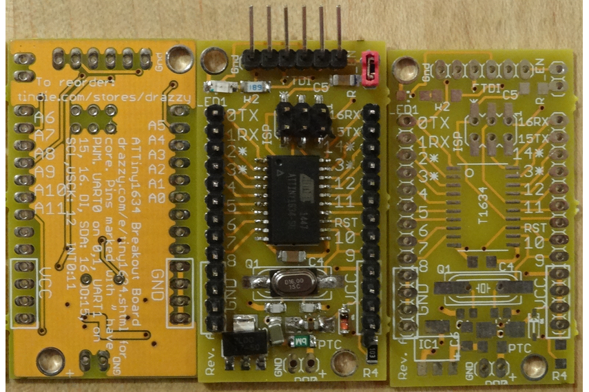
- Assembled Boards
- Bare Boards
- Azduino 1634 Ultramini - Coming Q2 2022- fits in a DIP-24 socket (2 pins missing on each side to leave room for the chip).
- Azduino USB 1634 Ultramini - Coming Q2 2022 - fits in a DIP-24 socket (2 pins missing on each side to leave room for the chip), with a MicroUSB socket extending past one end.
PB3 silicon errata workaround
If you have no need to use the WDT, but do have a need to use PB3 as an input, you can keep the WDT running by putting it into interrupt mode, with an empty interrupt, at the cost of just 10b of flash, an ISR that executes in 11 clock cycles every 8 seconds, and an extra 1-4uA of power consumption (negligible compared to what the chip consumes when not sleeping, and you'll turn it off while sleeping anyway - see below) - so the real impact of this issue is in fact very low, assuming you know about it and don't waste hours or days trying to figure out what is going on.
// put these lines in setup
CCP = 0xD8; //write key to configuration change protection register
WDTCSR = (1 << WDP3) | (1 << WDP0) | (1 << WDIE); //enable WDT interrupt with longest prescale option (8 seconds)
// put this empty WDT ISR outside of all functions
EMPTY_INTERRUPT(WDT_vect) // empty ISR to work around bug with PB3. EMPTY_INTERRUPT uses 26 bytes less than ISR(WDT_vect){;}
If you are using sleep modes, you also need to turn the WDT off while sleeping (both because the interrupts would wake it, and because the WDT is consuming power, and presumably that's what you're trying to avoid by sleeping). Doing so as shown below only uses an extra 12-16 bytes if you call it from a single place, 20 if called from two places, and 2 bytes when you call it thereafter, compared to calling sleep_cpu() directly in those places, as you would on a part that didn't need this workaround.
void startSleep() { //call instead of sleep_cpu()
  CCP = 0xD8; //write key to configuration change protection register
  WDTCSR = 0; //disable WDT interrupt
  sleep_cpu();
  CCP = 0xD8; // write key to configuration change protection register
  WDTCSR = (1 << WDP3) | (1 << WDP0) | (1 << WDIE); // enable WDT interrupt
}
Interrupt Vectors
This table lists all of the interrupt vectors available on the ATtiny 1634, as well as the name you refer to them as when using the ISR() macro. Be aware that a non-existent vector is just a "warning" not an "error" (for example, if you misspell a vector name) - however, when that interrupt is triggered, the device will (at best) immediately reset (and not cleanly - I refer to this as a "dirty reset") The catastrophic nature of the failure often makes debugging challenging.
Note: The shown addresses below are "byte addressed" as that has proven more readily recognizable. The vector number is the number you are shown in the event of a duplicate vector error, as well as the interrupt priority (lower number = higher priority), if, for example, several interrupt flags are set while interrupts are disabled, the lowest numbered one would run first. Notice that INT0 is (as always) the highest priority interrupt. Since these parts use 4-byte vectors.
| vect_num | Addr. | Vector Name | Interrupt Definition |
|---|---|---|---|
| 0 | 0x0000 | RESET_vect | Not an interrupt - this is a jump to the start of your code. |
| 1 | 0x0004 | INT0_vect | External Interrupt Request 0 |
| 2 | 0x0008 | PCINT0_vect | Pin Change Interrupt 0 (PORT A) |
| 3 | 0x0006 | PCINT1_vect | Pin Change Interrupt 1 (PORT B) |
| 4 | 0x0000 | PCINT2_vect | Pin Change Interrupt 2 (PORT C) |
| 5 | 0x0004 | WDT_vect | Watchdog Time-out (Interrupt Mode) |
| 6 | 0x0008 | Timer/Counter1 Input Capture | |
| 6 | 0x0008 | TIMER1_CAPT_vect | Alias - provided by ATTinyCore |
| 7 | 0x000C | Timer/Counter1 Compare Match A | |
| 7 | 0x000C | TIMER1_COMPA_vect | Alias - provided by ATTinyCore |
| 8 | 0x0010 | Timer/Counter1 Compare Match B | |
| 8 | 0x0010 | TIMER1_COMPB_vect | Alias - provided by ATTinyCore |
| 9 | 0x0014 | Timer/Counter1 Overflow | |
| 9 | 0x0014 | TIMER1_OVF_vect | Alias - provided by ATTinyCore |
| 10 | 0x0018 | Timer/Counter0 Compare Match A | |
| 10 | 0x0018 | TIMER0_COMPA_vect | Alias - provided by ATTinyCore |
| 11 | 0x0016 | Timer/Counter0 Compare Match B | |
| 11 | 0x0016 | TIMER0_COMPB_vect | Alias - provided by ATTinyCore |
| 12 | 0x0010 | Timer/Counter0 Overflow | |
| 12 | 0x0010 | TIMER0_OVF_vect | Alias - provided by ATTinyCore |
| 13 | 0x0014 | ANA_COMP_vect | Analog Comparator |
| 14 | 0x0018 | ADC_READY_vect | ADC Conversion Complete |
| 15 | 0x001C | USART0_RXS_vect | USART0 Rx Start |
| 16 | 0x0020 | USART0_RXC_vect | USART0 Rx Complete |
| 17 | 0x0024 | USART0_DRE_vect | USART0 Data Register Empty |
| 18 | 0x0028 | USART0_TXC_vect | USART0 Tx Complete |
| 19 | 0x0026 | USART1_RXS_vect | USART1 Rx Start |
| 20 | 0x0020 | USART1_RXC_vect | USART1 Rx Complete |
| 21 | 0x0024 | USART1_DRE_vect | USART1 Data Register Empty |
| 22 | 0x0028 | USART1_TXC_vect | USART1 Tx Complete |
| 23 | 0x002C | USI_STR_vect | USI START |
| 24 | 0x0030 | USI_OVF_vect | USI Overflow |
| 25 | 0x0034 | TWI_vect | Two-Wire Interface |
| 26 | 0x0038 | EE_RDY_vect | EEPROM Ready |
| 27 | 0x0036 | QTRIP_vect | QTouch |