Tulip Breadboard edition
October 8, 2024 · View on GitHub
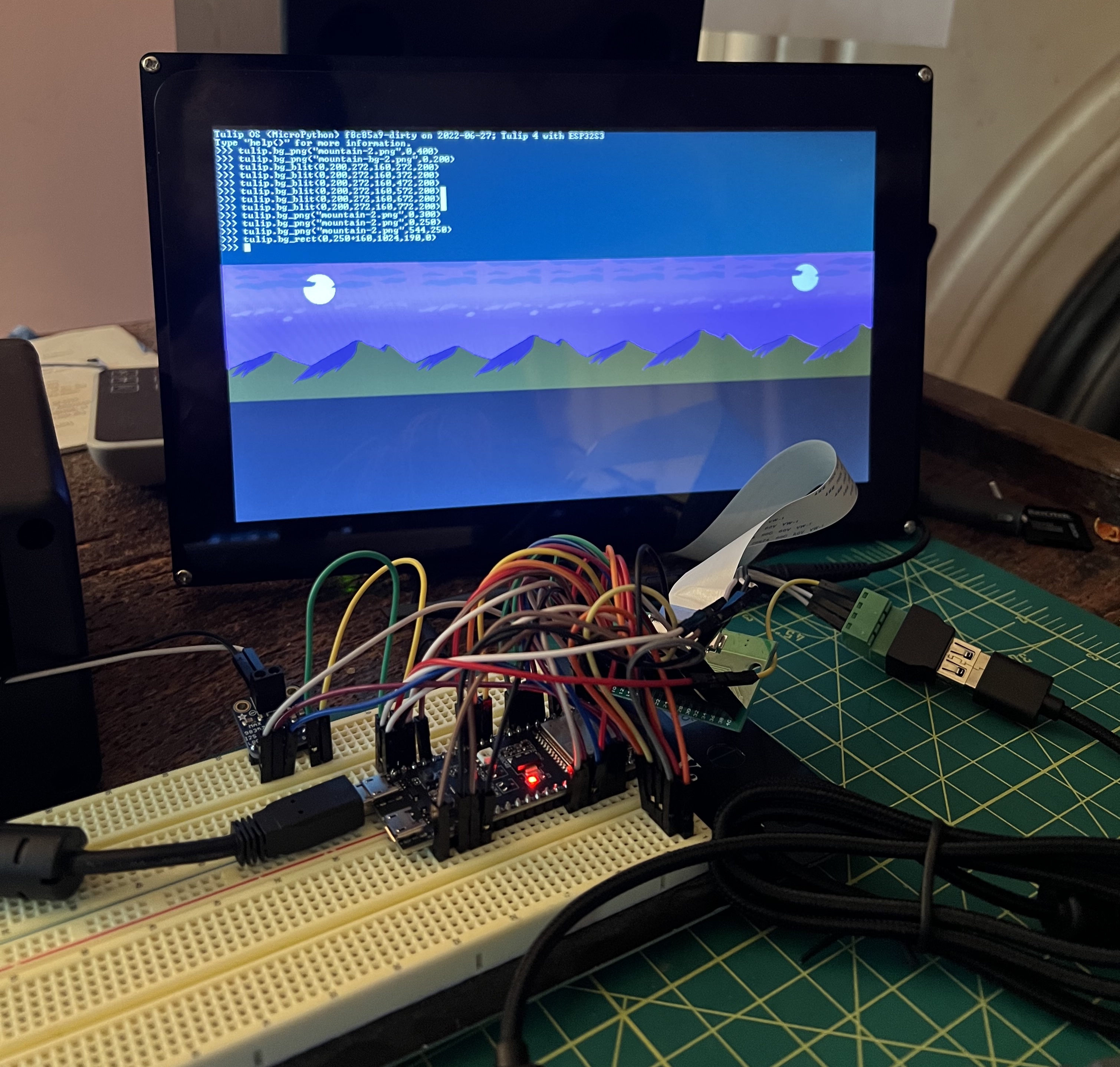
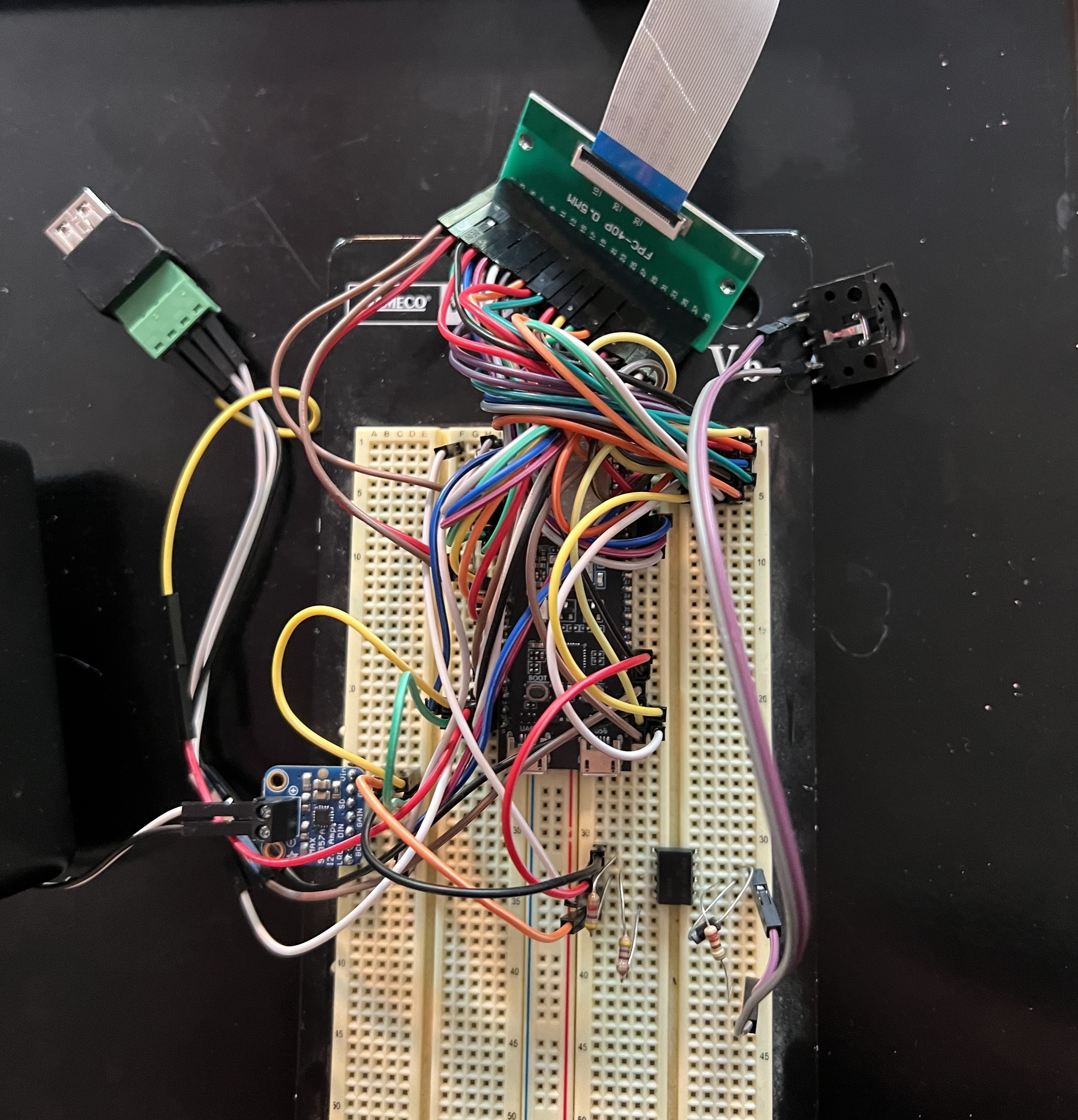
Tulip CC can be easily built with no soldering by connecting an ESP32S3 breakout board to a display and audio board. With a breadboard and a lot of jumper wires, you can put together Tulip in less than an hour.
If you'd rather make something more permanent, you can instead make a breakout board with just through hole solder, or a fully integrated surface mount board.
You'll need
- A breadboard
- ESP32-S3 WROOM-1 N32R8 dev board. The N32R8 has 32MB of flash. You can also use the N16R8 with 16MB of flash.
- This $58 RGB dot-clock 10.1" display with capacitive touch. Note other RGB dot clock displays of different sizes and resolutions can also work, but the pin numberings will be different and you'll have to update the resolution in our code.
- A 40-pin FPC header for the display.
- One of two choices for sound: either this mono I2S speaker amp board (you'll also need a 3W speaker) or this stereo line-out / headphone jack UDA1334 DAC.
- Almost any USB keyboard should work.
- If you want to support an optional NES or SNES joytstick, get the right connector.
- Connectors and random parts:
- 1 USB female A screw terminal
- 2 female 5-pin DIN MIDI jacks
- 1 6N138 optoisolator and an 8-pin socket
- 7 resistors:
R1: 4.7K,R2: 4.7K,R3: 4.7K,R4: 220,R5: 470,R6: 33,R7: 10.R4throughR7don't have to be precisely those numbers, find the closest number that you have. - 1 diode: 1N4001
Here's the pin connections you'll need to make. A note, These pin numbers for the display (D#) are to match the numbers on the side of the board the FPC connector is on, the side that reads FPC-40P 0.5MM.
| Label | ESP32 S3 Pin | Position on ESP32-S3-WROOM-1 | Connect to |
|---|---|---|---|
| Backlight PWM | 16 | Left row, 9th pin down (L9) | Display 6 (D6) |
| Data Enable | 42 | Right row, 6th pin down (R6) | D7 |
| VSYNC | 41 | R7 | D8 |
| HSYNC | 40 | R8 | D9 |
| LCD BL EN | 39 | R9 | D10 |
| PCLK | 14 | L20 | D11 |
| B7 | 21 | R18 | D13 |
| B6 | 12 | L18 | D14 |
| B5 | GND | L22 | D15 |
| G7 | 46 | L14 | D21 |
| G6 | 3 | L13 | D22 |
| G5 | 8 | L12 | D23 |
| R7 | 15 | L8 | D29 |
| R6 | 7 | L7 | D30 |
| R5 | 6 | L6 | D31 |
| 3v3 | 3v3 | L1 | D37 |
| GND | GND | L22 | D38 |
| 5V | 5V | L21 | D39 |
| 5V | 5V | L21 | D40 |
| Touch SDA | 18 | L11 | D4 |
| Touch SCL | 17 | L10 | D3 |
| Touch CTP INT | 5 | L5 | D1 |
| Touch CTP RST | N/C | N/C | D2 |
| USB 5V | 5V | L21 | USB 5V |
| USB D+ | 20 | R19 | USB D+ |
| USB D- | 19 | R20 | USB D- |
| USB GND | GND | L22 | USB GND |
| Audio LRC | 4 | L4 | Audio LRC |
| Audio BCLK | 1 | R4 | Audio BCLK |
| Audio DIN | 2 | R5 | Audio DIN |
| Audio GND | GND | L22 | Audio GND |
| Audio VIN | 5V | L21 | Audio VIN |
| MIDI in | 47 | R17 | MIDI TX |
| MIDI out | 11 | L17 | MIDI RX |
| MIDI 5V | 5V | L21 | MIDI 5v |
| MIDI GND | GND | L22 | MIDI GND |
| Joy CLOCK | 13 | L19 | Joy CLOCK |
| Joy LATCH | 48 | R16 | Joy LATCH |
| Joy DATA | 45 | R15 | Joy DATA |
| Joy 5V | 5V | L21 | Joy 5V |
| Joy GND | GND | L22 | Joy GND |
Wire the FPC cable to the displays "RGB" port. The included cable with the display works fine. The blue side should be facing up on both ends.
Also, you may want to ground all remaining display pins if you're seeing flickering. But make sure not to connect anything to D2, it stays not connected.
You'll want to see how to wire the MIDI in and out. That's R3, R4, R5, R6 and R7 along with the 6N138 and diode. (You can save some time buying a MIDI in/out breakout board like this one on Adafruit. and just wire it to MIDI in and out from the ESP directly.)
Touch SDA and Touch SCL need to be pulled up via 4.7K resistor to 3.3V. So run two resistors R1 and R2 from those pins on the ESP to 3.3V somewhere on the board.
After you're done assembling, read about how to compile and flash Tulip.
Any questions? Chat with us on our discussions page.