circuit-to-svg
August 18, 2026 · View on GitHub
A TypeScript library for converting Circuit JSON to Schematic, PCB and Assembly SVG representations.
Getting Started Contributor Video
npm add circuit-to-svg
# or...
bun add circuit-to-svg
Overview
This library provides functionality to convert Circuit JSON into SVG (Scalable Vector Graphics) representations. It supports both schematic and PCB (Printed Circuit Board), and Assembly layouts.
Installation
npm install circuit-to-svg
Usage
import { readFileSync, writeFileSync } from 'fs'
import { convertCircuitJsonToSchematicSvg } from 'circuit-to-svg'

const circuitJson = JSON.parse(readFileSync('circuit.json', 'utf8'))
const schematicSvg = convertCircuitJsonToSchematicSvg(circuitJson)

writeFileSync('schematic.svg', schematicSvg)
Explore the API sections below to render PCB, assembly, pinout, simulation, and solder paste views.
| Function | Description |
|---|---|
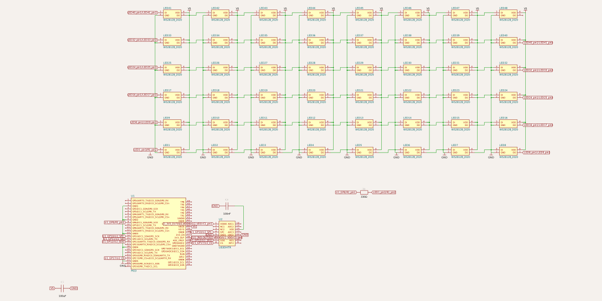
convertCircuitJsonToSchematicSvg | Generate schematic SVG output from Circuit JSON. |
convertCircuitJsonToSchematicSimulationSvg | Overlay simulation data on schematic diagrams. |
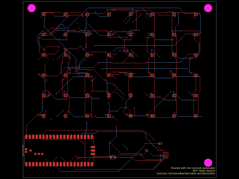
convertCircuitJsonToPcbSvg | Render PCB layouts as SVG graphics. |
convertCircuitJsonToSolderPasteMask | Create solder paste mask layers for fabrication. |
convertCircuitJsonToAssemblySvg | Produce assembly view SVGs for board visualization. |
convertCircuitJsonToPinoutSvg | Build annotated pinout diagrams for boards and modules. |
convertCircuitJsonToSimulationGraphSvg | Plot simulation experiment results as SVG graphs. |
API
convertCircuitJsonToSchematicSvg
convertCircuitJsonToSchematicSvg(circuitJson: AnyCircuitElement[], options?): string
Converts a schematic circuit description to an SVG string.
import { convertCircuitJsonToSchematicSvg } from 'circuit-to-svg'

const schematicSvg = convertCircuitJsonToSchematicSvg(circuitJson, {
  includeVersion: true,
})

Options
widthandheight– dimensions of the output SVG. Defaults to1200x600.grid– enable a schematic grid (true) or configure cell size and labels.labeledPoints– annotate specific coordinates with helper labels.colorOverrides– override portions of the schematic color palette.className– add one or more extra classes to the root schematic<svg>.css– append custom CSS to the generated schematic SVG.includeVersion– iftrue, add adata-circuit-to-svg-versionattribute to the root<svg>.
convertCircuitJsonToPcbSvg
convertCircuitJsonToPcbSvg(circuitJson: AnyCircuitElement[], options?): string
Converts a PCB layout description to an SVG string.
import { convertCircuitJsonToPcbSvg } from 'circuit-to-svg'

const pcbSvg = convertCircuitJsonToPcbSvg(circuitJson, {
  matchBoardAspectRatio: true,
  backgroundColor: '#1e1e1e',
  showPinNumbers: true,
})
Options
-
widthandheight– dimensions of the output SVG. Defaults to800x600. -
matchBoardAspectRatio– iftrue, adjust the SVG dimensions so the resulting aspect ratio matches thepcb_boardfound in the circuit JSON. -
backgroundColor– fill color for the SVG background rectangle. Defaults to"#000". -
drawPaddingOutsideBoard– iffalse, omit the board outline and extra padding around it. Defaults totrue. -
showPcbNotes– iffalse, hide allpcb_note*overlay primitives at render time. Defaults totrue. -
showPinNumbers– iftrue, annotate PCB pads with small gray pin numbers. Defaults tofalse. -
showSolderPaste– iftrue, renderpcb_solder_pasteprimitives. Defaults tofalse. -
shouldDrawErrors– iftrue, display visual error indicators (red diamonds with text) for error elements in the circuit JSON. Supports:pcb_trace_error– errors related to PCB tracespcb_footprint_overlap_error– errors for overlapping pads, plated holes, and holes (displays error indicators at each affected element with connecting lines)pcb_pad_trace_clearance_error– clearance errors between pads and tracespcb_via_trace_clearance_error– clearance errors between vias and traces
Defaults to
false. -
shouldDrawWarnings– iftrue, display yellow component highlights and warning messages for supported warning elements in the circuit JSON. Supportspcb_connector_not_in_accessible_orientation_warningandpcb_manual_edit_conflict_warning. Defaults tofalse. -
includeVersion– iftrue, add adata-circuit-to-svg-versionattribute to the root<svg>.
convertCircuitJsonToAssemblySvg
Converts circuit JSON into an assembly view of the board and components.
import { convertCircuitJsonToAssemblySvg } from 'circuit-to-svg'

const assemblySvg = convertCircuitJsonToAssemblySvg(circuitJson, {
  includeVersion: false,
})

Options
widthandheight– dimensions of the output SVG. Defaults to800x600.includeVersion– iftrue, add adata-circuit-to-svg-versionattribute to the root<svg>.
convertCircuitJsonToPinoutSvg
Generates pinout diagrams that call out ports, pads, and holes for boards or modules.
import { convertCircuitJsonToPinoutSvg } from 'circuit-to-svg'

const pinoutSvg = convertCircuitJsonToPinoutSvg(circuitJson)

Options
widthandheight– dimensions of the output SVG. Defaults to800x600.includeVersion– iftrue, add adata-circuit-to-svg-versionattribute to the root<svg>.
convertCircuitJsonToSchematicSimulationSvg
Overlays simulation results directly on the rendered schematic for easy debugging.
import { convertCircuitJsonToSchematicSimulationSvg } from 'circuit-to-svg'

const schematicSimulationSvg = convertCircuitJsonToSchematicSimulationSvg({
  circuitJson,
  simulation_experiment_id: 'simulation-experiment-id',
  simulation_transient_current_graph_ids: ['transient-current-graph-id'],
  simulation_transient_voltage_graph_ids: ['transient-graph-id'],
  schematicHeightRatio: 0.6,
})

Options
widthandheight– overall SVG dimensions. Defaults to1200x1200.schematicHeightRatio– ratio of the SVG dedicated to the schematic view. Defaults to0.55.schematicOptions– forward additional schematic rendering options (exceptwidth,height, andincludeVersion).simulation_transient_current_graph_ids– optional list of current graph IDs to render.simulation_transient_voltage_graph_ids– optional list of voltage graph IDs to render.includeVersion– iftrue, add adata-circuit-to-svg-versionattribute to the root<svg>.graphAboveSchematic– iftrue, place the simulation graph above the schematic instead of below (defaults tofalse).
convertCircuitJsonToSimulationGraphSvg
Creates standalone graphs for circuit simulation experiments.
import { convertCircuitJsonToSimulationGraphSvg } from 'circuit-to-svg'

const simulationGraphSvg = convertCircuitJsonToSimulationGraphSvg({
  circuitJson,
  simulation_experiment_id: 'simulation-experiment-id',
  simulation_transient_current_graph_ids: ['transient-current-graph-id'],
  simulation_transient_voltage_graph_ids: ['transient-graph-id'],
})

Options
widthandheight– SVG dimensions for the graph. Defaults to1200x600.simulation_transient_current_graph_ids– optional list of current graph IDs to render.simulation_transient_voltage_graph_ids– optional list of voltage graph IDs to render.includeVersion– iftrue, add adata-circuit-to-svg-versionattribute to the root<svg>.
convertCircuitJsonToSolderPasteMask
convertCircuitJsonToSolderPasteMask(circuitJson: AnyCircuitElement[], options: { layer: 'top' | 'bottom'; width?; height?; includeVersion? }): string
Produces top and bottom solder paste mask renderings suitable for stencil generation.
import { convertCircuitJsonToSolderPasteMask } from 'circuit-to-svg'

const solderPasteMaskSvg = convertCircuitJsonToSolderPasteMask(circuitJson, {
  layer: 'top',
})

Options
layer–'top' | 'bottom', chooses which solder paste layer to render. Defaults to'top'.widthandheight– dimensions of the output SVG. Defaults to800x600.includeVersion– iftrue, add adata-circuit-to-svg-versionattribute to the root<svg>.