CHAPTER 2 - BASIC
June 21, 2020 · View on GitHub
The BASIC of MSX2 has been upgraded: the new version is called MSX BASIC version 2.0. And, when using a disk system, MSX DISK-BASIC can be used, which consists of MSX BASIC version 2.0 and additional instructions for disk operations. The following sections describe these two versions of BASIC.
Index
1.1 Instructions of MSX BASIC version 2.0
1.2 Instructions of MSX DISK-BASIC
2. DIFFERENCES IN MSX BASIC VERSION 2.0
2.1 Additions or Modifications to Screen Mode
2.2 Additions or Modifications for the Colour Specification
2.3 Additions or Modifications for the Character Display
2.4 Additions or Modifications for the Graphics Display
2.5 Additions or modifications for VDP access
2.7 Additions or Modifications for Sprite
2.8 Additions for Optional Features
2.9 Additions for Timer Features
2.10 Additions for Memory Switch
3. INTERNAL STRUCTURE OF BASIC
3.2 Detailed View of the User's Area
3.3 Storage format of BASIC programs
4. LINKING WITH ASSEMBLY LANGUAGE PROGRAMS
4.2 Data Exchange by the Argument and Return Value of USR Function
5. NOTES ON SOFTWARE DEVELOPMENT
1. LIST OF INSTRUCTIONS
First of all, the sentence and function for each instruction of BASIC are listed. Each instruction is listed in the format shown in Figure 2.1.
Figure 2.1 Instruction list format

(a) Syntax of instructions
If there is an "*" followed by a keyword, it indicates that the syntax or function of the instruction has just been modified after version 1.0, or that the instruction has been added to version 2.0.
Descriptions of sentences use the following notational conventions.
* [item] .............. the item is optional
* [, item ... ] ....... more items having the same form may appear
* [item1 | item2] ..... choose item1 or item2
And <filename>, which is used in the sentence, is a string specifying I/O devices or files for input/output in the format listed below. <Filename> for a cassette files is a string consisting of any combination of up to 6 characters. <filename> for disk or RAM disk is a string, whose form is "<filename (up to 8 characters)> + <filename extension (up to 3 characters)>". <drive> is one of characters from A to H (depending on the number of drives connected).
"CAS: <filename>" ..... Cassette file
"MEM: <filename>" ..... RAM disk
"CRT:" ................ Text screen
"GRP:" ................ Graphic screen
"LPT:" ................ Printer
"<drive>:<filename>" .. Disk file
(b) Instruction type
There are four types of instructions:
* Function ............ Returns a certain value depending on the given parameter(s).
* System variable ..... Variables available from BASIC. Generally, assignment is allowed.
* Statement ........... Takes a certain action.
* Command ............. Gives an instruction to BASIC interpreter itself.
(c) Function or action of instruction
The following list gives a brief description of the action for each instruction. More detailed descriptions about instructions which have been modified or added at version 2.0 are given in section 2.
1.1 Instructions of MSX BASIC version 2.0
--- A ---
| Format | Type | Function or action |
|---|---|---|
ABS (<expression>) | Function | Returns absolute value of <expression>. |
ASC (<string>) | Function | Returns the code of the first character of <string>. |
ATN (<expression>) | Function | Returns arc tangent of <expression> in radians. |
AUTO [<linenumber>[, <increment>]] | Command | Produces line numbers automatically. |
--- B ---
| Format | Type | Function or action |
|---|---|---|
* BASE (<expression>) | System variable | Contains the table address of the screen assigned on VRAM. |
BEEP | Statement | Produces beep to the audio terminal. |
BIN$ (<expression>) | Function | Converts the value of <expression> to a string of binary expression, then returns its result. |
BLOAD "<filename>"[,R[,offset]] | Command | Loads an assembly language program. |
BSAVE "<filename>",<start address>,<end address>[,<execution address>] | Command | Saves an assembly language program. |
--- C ---
| Format | Type | Function or action |
|---|---|---|
CALL <extended statement name>[(<argument>[,<argument>...])] | Statement | Calls the extended statements by inserting various cartridges. |
* CALL MEMINI [(<upper limitation of RAM disk>)] | Statement | Specifies the upper limit of memory for Ram disk. |
* CALL MFILES | Statement | Lists file names in RAM disk. |
* CALL MKILL ("<filename>") | Statement | Deletes a file in RAM disk. |
* CALL MNAME ("<old filename>" AS "<new filename>") | Statement | Renames a file in RAM disk. |
CDBL (<expression>) | Function | Converts the value of <expression> to a double precission real value and returns its result. |
CHR$ (<expression>) Returns a character which has the code of | Function | <expression> value. |
CINT (<expression>) | Function | Converts the value of <expression> to an integer value and returns its result. |
* CIRCLE {(X,Y) | STEP(X,Y)},<radius>[, <colour>[, <start angle>[, <end angle>[, <proportion>]]]] | Statement | Draws a circle whose center is at (X,Y) and whose size depends on <radius>. |
CLEAR [<size of string area>[, <upper limitation of memory>]] | Statement | Initialises variables and sets the size of memory area. |
CLOAD ["<filename>"] | Command | Loads a program from cassette. |
CLOAD? ["<filename>"] | Command | Compares a program on cassette with the one in memory. |
CLOSE [[#]<filenumber>[, [#]<filenumber>...]] | Command | Closes a file represented by <filenumber>. |
CLS | Statement | Clears screen. |
* COLOR [<foreground colour>[, <background colour>[, <border colour>]]] | Statement | Specifies the colours of each part of the screen. |
* COLOR [=NEW] | Statement | Initialises the palette. |
* COLOR = (<palette number>, <red brightness>, <green brightness>, <blue brightness>) | Statement | Sets the palette colour. |
* COLOR = RESTORE | Statement | Puts the contents of the colour palette storage table into the palette register. |
* COLOR SPRITE (<sprite plane number>)=<colour> | Statement | Sets the colour to the sprite of <sprite plane number> to the specified colour. |
* COLOR SPRITE$ (<sprite plane number>)=<string expression> | Statement | Sets the colour of each horizontal line of the sprite using <string expression>. |
CONT | Command | Resumes the execution of the program which has been stopped. |
* COPY <source> TO <destination> | Statement | Transfers the screen data among the screen, array, and disk file. |
* COPY SCREEN [<mode>] | Statement | Writes colour bus data into VRAM (optional). |
COS (<expression>) | Function | Returns the cosine value of <expression (in radians)>. |
CSAVE "<filename>"[, <baud rate>] | Command | Saves a program to cassette. |
CSGN (<expression>) | Function | Converts the value of <expression> to a single precision real value, and returns its result. |
CSRLIN | System variable | Contains the vertical screen location of the cursor. No assignment is allowed. |
--- D ---
| Format | Type | Function or action |
|---|---|---|
DATA <constant>[, <constant>...] | Statement | Prepares data to be read by READ statement. |
DEF FN <name> [(<argument>[, <argument>...])]=<function-definitive expression> | Statement | Defines a user-defined function. |
DEFINT <character range>[, <character range>...] | Statement | Declares the specified variable(s) as integer type. |
DEFSNG <character range>[, <character range>...] | Statement | Declares the specified variable(s) as single precision real type. |
DEFDBL <character range>[, <character range>...] | Statement | Declares the specified variable(s) as double precision real type. |
DEFSTR <character range>[, <character range>...] | Statement | Declares the specified variable(s) as character type. |
DEF USR [<number>]=<start address> | Statement | Defines the starting address for the execution of assembly language routine, called by USR function. |
DELETE {[<start linenumber>-<end linenumber>] | <linenumber> | -<end linenumber>} | Command | Deletes the specified portion of the program. |
DIM <variable name> (<maximum subscript value>[, <maximum subscript value>...]) | Statement | Defines an array variable and allocates it into memory. |
DRAW <string expression> | Statement | Draws a line or lines on the screen according to <string expression (DRAW macro)>. |
--- E ---
| Format | Type | Function or action |
|---|---|---|
END | Statement | Ens the program, close all files, and returns to the command level. |
EOF (<filenumber>) | Function | Checks if the file is finished and returns -1 if at the end of file. |
ERASE <array variable name>[, <array variable name>...] | Statement | Deletes the array variable(s). |
ERL | System variable | Contains the error code for the preceding error. No assignment is allowed. |
ERR | System variable | Contains the line number of the previous error. No assignment is allowed. |
ERROR <error code> | Statement | Puts the program into the error condition. |
EXP (<expression>) | Function | Returns the exponent (power) of the natural exponential form of <expression>. |
--- F ---
| Format | Type | Function or action |
|---|---|---|
FIX (<expression>) | Function | Returns the value of <expression>, without any decimal fractions. |
FOR <variable name> = <initial value> TO <end value> [STEP <increment>] | Statement | Repeats the execution from FOR statement to NEXT statement for the specified times. |
FRE ({<expression> | <string expression>}) | Function | Returns the size of unused user's area or unused character area. |
--- G ---
| Format | Type | Function or action |
|---|---|---|
* GET DATE <string variable name>[, A] | Statement | Assigns date into a string variable. |
* GET TIME <string variable name>[, A] | Statement | Assigns time into a string variable. |
GOSUB <linenumber> | Statement | Calls the subroutine at <linenumber>. |
GOTO <linenumber> | Statement | Jumps to <linenumber>. |
--- H ---
| Format | Type | Function or action |
|---|---|---|
HEX$ (<expression>) | Function | Converts the value of <expression> to a string of hexadecimal expression, then returns its result. |
--- I ---
| Format | Type | Function or action |
|---|---|---|
IF <condition> THEN {<statement> | <linenumber>} [ELSE {<statement> | <linenumber>}] | Statement | Judges the condition. If <condition> is not zero, it is true. |
IF <condition> GOTO <linenumber> [ELSE {<statement> | <linenumber>}] | Statement | Judges the condition. If <condition> is not zero, it is true. |
INKEY$ | Function | Returns a character when a key is being pressed, or when not, returns null string. |
INP (<port number>) | Function | Reads the port specified by <port number> and returns its result. |
INPUT ["<prompt statement>";]<variable name>[, <variable name>...] | Statement | Assigns data input from keyboard into the specified variable(s). |
INPUT #<filenumber>, <variable name>[, <variable name>...] | Statement | Reads data from the file and assigns the data into the specified variable(s). |
INPUT$ (<number of characters>[, [#]<filenumber>]) | Function | Reads the specified size of string from the keyboard or file. |
INSTR ([<expression>,]<string expression 1>,<string expression 2>) | Function | Searches <string expression 2> from the left of <string expression 1>, and returns its location if found, otherwise zero. <Expression> is the character location to start searching. |
INT (<expression>) | Function | Returns the largest integer less than <expression>. |
INTERVAL {ON | OFF | STOP} | Statement | Allows, suppresses, or suspends the timer interrupt. |
--- K ---
| Format | Type | Function or action |
|---|---|---|
KEY <key number>,<string> | Command | Redefines a function key. |
KEY LIST | Command | Displays the contents of function keys. |
KEY (<key number>){ON | OFF | STOP} | Statement | Allows, supresses, os suspends the function key interrupt. |
KEY {ON | OFF} | Statement | Specifies whethter to display the contents of function keys at the bottom of the screen. |
--- L ---
| Format | Type | Function or action |
|---|---|---|
LEFT$ (<string expression>,<expression>) | Function | Gets <expression> characters from the left of <string expression>. |
LEN (<string expression>) | Function | Returns the number of characters of <string expression>. |
[LET] <variable name> = <expression> | Statement | Assigns the value of <expression> to the variable. |
* LINE [{(X1,Y1) | STEP(X1,Y1)}] - {(X2,Y2) | STEP(X2,Y2)}[, <colour> [, {B|BF}[, <logical operation>]]] | Statement | Draws a line or a rectangle on the screen. |
LINE INPUT ["<prompt statement>";]<string variable name> | Statement | Assigns a whole line of string data from the keyboard into the string variable. |
LINE INPUT# <filenumber>, <string variable name> | Statement | Reads data in lines from the file and assigns the data into the string variable. |
LIST [[<linenumber>] - [<linenumber>]] | Command | Displays the program in memory on the screen. |
LLIST [[<linenumber>] - [<linenumber>]] | Command | Sends the program in memory to the printer. |
LOAD "<filename>" [,R] | Command | Loads a program saved in ASCII format. |
* LOCATE [<X-coordinate>[, <Y-coordinate>[, <cursor switch>]]] | Statement | Locates the cursor on the text screen. |
LOG (<expression>) | Function | Returns the natural logarithm of <expression>. |
LPOS (<expression>) | System variable | Contains the location of the printer head. No assignment is allowed. |
LPRINT [<expression>[{; | ,}<express]ion>...] | Statement | Outputs characters or numerical values to the printer. |
LPRINT USING <form>; <expression>[{; | ,}<expression>...] | Statement | Outputs characters or numerical values through the printer according to <form>. |
--- M ---
| Format | Type | Function or action |
|---|---|---|
MAXFILES = <number of files> | Statement | Sets the number of files to be opened. |
MERGE "<filename>" | Command | Merges the program in memory with the program saved in ASCII format (in external storage device). |
MID$ (<string expression>, <expression 1>[, <expression 2>]) | Function | Returns <expression 2> character(s) starting from the <expression 1>th position of <string expression>. |
MID$ (<string variable name>, <expression 1>[, <expression 2>]) = <string expression> | Statement | Defines <string expression> using <expression 2> character(s) from the <expression 1>th position of <string variable name>. |
MOTOR [{ON | OFF}] | Statement | Turns the motor of cassette ON and OFF. |
--- N ---
| Format | Type | Function or action |
|---|---|---|
NEW | Command | Deletes the program in meory and clears variables. |
NEXT [<variable name>[, <variable name>...]] | Statement | Indicates the end of FOR statement. |
--- O ---
| Format | Type | Function or action |
|---|---|---|
OCT$ (<expression>) | Function | Converts the value of <expression> to the string of octal expression and returns its result. |
ON ERROR GOTO <linenumber> | Statement | Defines the line to begin the error handling routine. |
ON <expression> GOSUB <linenumber>[, <linenumber>...] | Statement | Executes the subroutine at <linenumber> according to <expression>. |
ON <expression> GOTO <linenumber>[, <linenumber>...] | Statement | Jumps to <linenumber> according to <expression>. |
ON INTERVAL = <time> GOSUB <linenumber> | Statement | Defines the timer interrupt interval and the line to begin the interrupt handling routine. |
ON KEY GOSUB <linenumber>[, <linenumber>...] | Statament | Defines the line to begin the function key interrupt handling routine. |
ON SPRITE GOSUB <linenumber> | Statement | Defines the line to begin the piled-sprite interrupt handling routine. |
ON STOP GOSUB <linenumber> | Statament | Defines the line to begin the CTRL+STOP key interrupt handling routine. |
ON STRING GOSUB <linenumber>[, <linenumber>...] | Statement | Defines the line to begin the trigger button interrupt handling routine. |
OPEN "<filename>" [FOR <mode>] AS #<filenumber> | Statement | Opens the file in the specified mode. |
OUT <port number>,<expression> | Statement | Sends data to the output port specified by <port number>. |
--- P ---
| Format | Type | Function or action |
|---|---|---|
* PAD (<expression>) | Function | Examines the state of tablet, mouse, light pen, or track ball specified by <expression>, then returns its result. |
* PAINT {(X,Y) | STEP(X,Y)}[, <colour>[, <border colour>]] | Statement | Paints the area surrounded by specified <border colour> using <colour>. |
PDL (<paddle number>) | Function | Returns the state of the paddle which has the specified number. |
PEEK (<address>) | Function | Returns the contents of one byte of the memory specified by <address>. |
PLAY <string expression 1>[, <string expression 2>[, <string expression 3>]] | Statement | Plays the music by <string expression (music macro)>. |
PLAY (<voice channel>) | Function | Examines whethter the music is being played and returns its result (if in play, -1 is returned). |
POINT (X,Y) | Function | Returns the colour of the dot specified by coordinate (X,Y). |
POKE <address>,<data> | Statement | Writes one byte of <data> into the memory specified by <address>. |
POS (<expression>) | System variable | Contains the horizontal location of the cursor on the text screen. No assignment is allowed. |
* PRESET {(X,Y) | STEP(X,Y)}[, <colour>[, <logical operation>]] | Statement | Erases the dot specified by coordinate (X,Y) on the graphic screen |
PRINT [<expression [{; | ,}<expression>...] | Statement | Displays characters of numbers on the screen. |
PRINT USING <form>; <expression>[{; | ,}<expression>...] | Statement | Displays characters or numbers on the screen according to <form>. |
PRINT #<filenumber>, [<expression>[{; | ,}<expression>...]] | Statement | Writes characters or numbers to the file specified by <file number>. |
PRINT #<filenumber>, USING <form>; <expression>[{; | ,}<expression>...] | Statement | Writes characters or numbers to the file specified by <file number> according to <form>. |
PSET {(X,Y) | STEP(X,Y)}[, <colour>[, <logical operation>]] | Statement | Draws the dot in the coordinate specified by (X,Y) on the graphic screen. |
* PUT KANJI [(X,Y)],<JIS kanji code>[, <colour>[, <logical operation> [, <mode>]]] | Statement | Displays the kanji on the screen (KANJI ROM is required). |
* PUT SPRITE <sprite plane number>[, {(X,Y) | STEP(X,Y)}[, <colour>[, <sprite pattern number>]]] | Statement | Displays the sprite pattern. |
--- R ---
| Format | Type | Function or action |
|---|---|---|
READ <variable name>[, <variable name>...] | Statement | Reads data from DATA statement(s) and assigns the data to the variable(s). |
REM [<comment>] | Statement | Puts the comment in the program. |
RENUM [<new linenumber>[, <old linenumber>[, <increment>]]] | Command | Renumbers the line numbers. |
RESTORE [<linenumber>] | Statement | Specifies the line to begin reading DATA by READ statement. |
RESUME {[0] | NEXT | <linenumber>} | Statement | Ends the error recovery routine and resumes execution of the program. |
RETURN [<linenumber>] | Statement | Returns from a subroutine. |
RIGHT$ (<string expression>, <expression>) | Function | Gets <expression> characters from the right of <string expression>. |
RND [(<expression>)] | Function | Returns a random number between 0 and 1. |
RUN [<linenumber>] | Command | Executes the program from <linenumber>. |
--- S ---
| Format | Type | Function or action |
|---|---|---|
SAVE "<filename>" | Command | Saves the program in ASCII format. |
* SCREEN <screen mode>[, <sprite size>[, <key click switch>[, <cassette baud rate>[, <printer option>[, <interlace mode>]]]]] | Statement | Sets the screen mode and so on. |
* SET ADJUST (<X-coordinate offset>, <Y-coordinate offset>) | statement | Changes the display location of the screen. Ranges from -7 to 8. |
* SET BEEP <timbre>, <volume> | Statement | Selects the BEEP tone. Ranges from 1 to 4. |
* SET DATE <strign expression>[, A] | Statement | Sets a date. "A" is the specification of alarm. |
* SET PAGE <display page>, <active page> | Statement | Specifies the page to display and the page to read and write data to. |
* SET PASSWORD <string expression> | Statement | Sets a password. |
* SET PROMPT <string expression> | Statement | Sets a prompt (up to 8 characters). |
* SET SCREEN | Statement | Reserves the parameters of the current settings of SCREEN statement. |
* SET TIME <string expression>[, A] | Statement | Sets time. "A" is the alarm specification. |
* SET VIDEO [<mode>[, <Ym>[, <CB>[, <sync>[, <voice>[, <video input>[, <AV control>]]]]]]] | Statement | Sets superimposing and other modes (optional). |
SGN (<expression>) | Function | Examines the sign of <expression> and returns its result (positive=1, zero=0, negative=-1). |
SIN (<expression>) | Function | Returns the sine of <expression> in radians. |
SOUND <register number>,<data> | Statement | Writes data to the register of PSG. |
SPACE$ (<expression>) | Function | Returns a string containing <expression> spaces. |
SPC (<expression>) | Function | Produces <expression> spaces; used in the instructions of PRINT family. |
SPRITE {ON | OFF | STOP} | Statement | Allows, supresses, or suspends the piled-sprite interrupt. |
SPRITE$ (<sprite pattern number>) | System variable | Contains the sprite pattern. |
SQR (<expression>) | Function | Returns the square root of <expression>. |
STICK (<joystick number>) | Function | Examines the direction of the joystick and returns its result. |
STOP | Statement | Stops the execution of the program. |
STRIG (<joystick number>) | Function | Examines the state of the trigger button and returns its result. |
STRIG (<joystick number>) {ON | OFF | STOP} | Statement | Allows, supresses, or suspends interrupts from the trigger button. |
STR$ (<expression>) | Function | Converts the value of <expression> to a string decimal expression and returns its result. |
STRING$ (<expression 1>, {<string expression> | <expression 2>} | Function | Converts the leading character of <string expression> or the character containing the code <expression 2> to a string whose length is <expression 1>, and returns the string. |
SWAP <variable name>, <variable name> | Statement | Exchanges the value of two variables. |
--- T ---
| Format | Type | Function or action |
|---|---|---|
TAB (<expression>) | Function | Produces the specified spaces in PRINT instructions. |
TAN (<expression>) | Function | Returns the tangent of <expression> in radians. |
TIME | System variable | Contains the value of the interval timer. |
TRON | Command | Keeps displaying the line numbers of the program currently being executed. |
TROFF | Command | Cancels TRON and stops displaying the line numbers. |
--- U ---
| Format | Type | Function or action |
|---|---|---|
USR [<number](<argument>) | Function | Calls the assembly language routine. |
--- V ---
| Format | Type | Function or action |
|---|---|---|
VAL (<string expression>) | Function | Converts <string expression> to a numerical value and returns its result. |
VARPTR (<variable name>) | Function | Returns the address containing the variable. |
VARPTR (#<filenumber>) | Function | Returns the starting address of the file control block. |
* VDP (<register number>) | System variable | Writes/reads data to/from the VDP registers. |
* VPEEK (<address>) | Function | Reads data from <address> in VRAM. |
* VPOKE (<address>) | Statement | Writes data to <address> in VRAM. |
--- W ---
| Format | Type | Function or action |
|---|---|---|
WAIT <port number>, <expression 1>[, <expression 2>] | Statement | Stops the execution until data of the input port grows to the specified value. |
* WIDTH <number> | Statement | Specifies the number of characters per line in the display screen. |
1.2 Instructions of MSX DISK-BASIC
Note: Instructions marked with "**" have been added to version 2 of MSX DISK-BASIC and are not available in version 1.
--- B ---
| Format | Type | Function or action |
|---|---|---|
* BLOAD "<filename>"[{[, R] | [, S]}[, <offset>]] | Command | Loads the assembly language program or screen data from a file. |
* BSAVE "<filename>", <start address>, <end address>[, {<execution address> | S}] | Command | Saves the assembly language program or screen data in a file. |
--- C ---
| Format | Type | Function or action |
|---|---|---|
CLOSE [[#]<filenumber>[, [#]<filenumber>...]] | Statement | Closes the file specified by <filenumber>. |
** CALL CHDRV ("<drive name>:") | Command | Sets the drive specified by <drive name> as the default drive. |
** CALL CHDIR ("<directory path>") | Command | Changes to the directory specified by <directory path>. |
CALL FORMAT | Command | Formats the floppy disk. |
** CALL MKDIR ("<directory name>") | Command | Creates the directory with the name specified in <directory name> in the current directory. |
** CALL RAMDISK (<size in kilobytes>[, <variable name>]) | Command | Tries to crate the DOS 2 RAM disk of the specified size, and returns in the variable (if specified) the actual size of the RAM disk created. |
** CALL RMDIR ("<directory name>") | Command | Deletes the directory specified in <directory name>. If the directory is not empty, "File already exists" error will be returned. |
CALL SYSTEM | Command | Returns to MSX-DOS. |
** CALL SYSTEM [("<filename>")] | Command | Returns to MSX-DOS and executes the DOS command <filename> if it is specified. |
COPY "<filename 1>"[ TO "<filename 2>"] | Command | Copies the contents of <filename 1> to the file specified by <filename 2>. |
CVD (<8-byte string>) | Function | Converts the string to the double precision real value and returns its result. |
CVI (<2-byte string>) | Function | Converts the string to the integer value and returns its result. |
CVS (<4-byte string>) | Function | Converts the string to the single precision real value and returns its result. |
--- D ---
| Format | Type | Function or action |
|---|---|---|
DSKF (<drive number>) | Function | Returns the unused portions of the disk in clusters. |
DSKI$ (<drive number>, <sector number>) | Function | Reads the specified sector of the specified drive to the memory area indicated by address &HF351, and returns a null string. |
DSKO$ (<drive number>, <sector number>) | Statement | Writes 512 bytes starting from address indicated by &HF351 to the specified sector of the specified drive. |
--- E ---
| Format | Type | Function or action |
|---|---|---|
EOF (<filenumber>) | Function | Checks if the file has ended and returns -1 if at the end of file. |
--- F ---
| Format | Type | Function or action |
|---|---|---|
FIELD [#]<filenumber>, <field width> AS <string variable name>[, <field width> AS <string variable name>...] | Statement | Assigns the string variable name to the random input/output buffer. |
FILES ["<filename>"] | Command | Displays the name of the file matched with <filename> on the screen. |
** FILES ["<filename>"][,L] | Command | Displays the name of the file matched with <filename> on the screen, and also the attributes and the size of the file if "L" is specified. |
--- G ---
| Format | Type | Function or action |
|---|---|---|
GET[#]<filenumber>[, <record number>] | Statement | Reads one record from the random file to the random input/output buffer. |
--- I ---
| Format | Type | Function or action |
|---|---|---|
INPUT #<filenumber>, <variable name>[, <variable name>...] | Statement | Reads data from the file. |
INPUT$ (<the number of characters>[, [#]<filenumber>]) | Function | Gets the string of the specified length from the file. |
--- K ---
| Format | Type | Function or action |
|---|---|---|
KILL "<filename>" | Command | Delets the file specified by <filename>. |
--- L ---
| Format | Type | Function or action |
|---|---|---|
LFILES ["<filename>"] | Command | Sends the name of the file matched with <filename> to the printer. |
** LFILES ["<filename>"][,L] | Command | Sends the name of the file matched with <filename> to the printer, and also the attributes and the size of the file if "L" is specified. |
LINE INPUT #<file number>, <string variable name> | Statement | Reads lines of data from the file to the string variable. |
LOAD "<filename>"[, R] | Command | Loads the program into memory. |
LOC (<filenumber>) | Function | Returns the record number of the most recently accessed location of the file. |
LOF (<filenumber>) | Function | Returns the size of the specified file in bytes. |
LSET <string variable name>=<string expression> | Statement | Stores data padded on the left in the random input/output buffer. |
--- M ---
| Format | Type | Function or action |
|---|---|---|
MAXFILES = <the number of files> | Statement | Declares the maximum number of files that can be opened. |
MERGE "<filename>" | Command | Merges the program in memory with the program saved in ASCII format. |
MKD$ (<double precision real value>) | Function | Converts the double precision real value to the character code corresponding to the internal expression. |
MKI$ (<integer value>) | Function | Converts the integer value to the character code corresponding to the internal expression. |
MKS$ (<single precision real value>) | Function | Converts the single precision real value to the character code corresponding to the internal expression. |
--- N ---
| Format | Type | Function or action |
|---|---|---|
NAME "<filename 1>" AS "<filename 2>" | Command | Renames the name of a file. |
--- O ---
| Format | Type | Function or action |
|---|---|---|
OPEN "<filename>"[FOR <mode>] AS #<filenumber>[LEN = <record length>] | Statement | Opens the file. |
--- P ---
| Format | Type | Function or action |
|---|---|---|
PRINT #<filenumber>, [<expression>[{; | ,}<expression>...]] | Statement | Sends data to the sequential file. |
PRINT #<filenumber>, USING <form>; <expression>[{; | ,}<expression>...]] | Statement | Sends data to the sequential file according to the form. |
PUT [#]<filenumber>[, <record number>] | Statement | Sends data of the random input/output buffer to the random file. |
--- R ---
| Format | Type | Function or action |
|---|---|---|
RSET <string varibale name>=<string expression> | Statement | Stores data padded on the right in the random input/output buffer. |
RUN "<filename>"[, R] | Command | Loads a program from the disk and executes it. |
--- S ---
| Format | Type | Function or action |
|---|---|---|
SAVE "<filename>"[, A] | Command | Saves a program. The program is saved in ASCII format when "A" is specified. |
--- V ---
| Format | Type | Function or action |
|---|---|---|
VARPTR (#<filenumber>) | Function | Returns the starting address of the file control block. |
2. DIFFERENCES IN MSX BASIC VERSION 2.0
A great deal of functions in MSX BASIC version 2.0 have been added or modified when compared with MSX BASIC version 1.0. They are either the functions that are added or modified with the version-up of VDP (Video Display Processor) or the functions that are added or modified because of the various hardware features such as RAM disk, clock, or memory switch; especially, the alternation of VDP affects, most of the statement for the screen display.
This section picks up these statements and indicates the additions or the modifications. In the following descriptions, "MSX1" means MSX BASIC version 1.0 and "MSX2" for MSX BASIC version 2.0.
2.1 Additions or Modifications to Screen Mode
SCREEN <screen mode>[, <sprite size>[, <key click switch>[, <cassette baud rate>[, <printer option>[, <interlace mode>]]]]]
<Screen mode> and <interlace mode> have been modified.
<Screen mode> may be specified from 0 to 8. Modes from 0 to 3 are the same as MSX1 and the rest have been added. When specifying a screen mode, in BASIC it is called "SCREEN MODE", which is somewhat different from "screen mode" which is used by VDP internally. Table 2.1 shows these correspondences and meanings. The difference between screen modes 2 and 4 is only in the sprite display functions.
Table 2.1 Correspondances of BASIC screen (SCREEN) modes and VDP screen modes
-----------------------------------------------------------------------------
|              |             |                   Meaning                    |
|     BASIC    |    VDP      |----------------------------------------------|
|     mode     |    mode     |    Dots or     | Display colours |   Screen  |
|              |             |   characters   | at a time       |   format  |
|--------------+-------------+----------------+-----------------+-----------|
| SCREEN 0 (1) | TEXT 1      |  40 x 24 chars |    2 from 512   | Text      |
|--------------+-------------+----------------+-----------------+-----------|
| SCREEN 0 (2) | TEXT 2      |  80 x 24 chars |    2 from 512   | Text      |
|--------------+-------------+----------------+-----------------+-----------|
| SCREEN 1     | GRAPHIC 1   |  32 x 24 chars |   16 from 512   | Text      |
|--------------+-------------+----------------+-----------------+-----------|
| SCREEN 2     | GRAPHIC 2   | 256 x 192 dots |   16 from 512   | High res. |
|              |             |                |                 | graphics  |
|--------------+-------------+----------------+-----------------+-----------|
| SCREEN 3     | MULTICOLOUR |  64 x  48 dots |   16 from 512   | Low res.  |
|              |             |                |                 | graphics  |
|--------------+-------------+----------------+-----------------+-----------|
| SCREEN 4     | GRAPHIC 3   | 256 x 192 dots |   16 from 512   | High res. |
|              |             |                |                 | graphics  |
|--------------+-------------+----------------+-----------------+-----------|
| SCREEN 5     | GRAPHIC 4   | 256 x 212 dots |   16 from 512   | Bit map   |
|              |             |                |                 | graphics  |
|--------------+-------------+----------------+-----------------+-----------|
| SCREEN 6     | GRAPHIC 5   | 512 x 212 dots |    4 from 512   | Bit map   |
|              |             |                |                 | graphics  |
|--------------+-------------+----------------+-----------------+-----------|
| SCREEN 7     | GRAPHIC 6   | 512 x 212 dots |   16 from 512   | Bit map   |
|              |             |                |                 | graphics  |
|--------------+-------------+----------------+-----------------+-----------|
| SCREEN 8     | GRAPHIC 7   | 256 x 212 dots |   256           | Bit map   |
|              |             |                |                 | graphics  |
-----------------------------------------------------------------------------
Specifying <interlace mode> enables to set the interlace functions of VDP (see Table 2.2). In the alternate screen display mode, the display page specified in "SET PAGE" must be odd. In this case the display page and the page of which the number is smaller by one is displayed alternately.
Table 2.2 Differences of display function in the interlace mode
-----------------------------------------------------------------
|  Interlace mode  |             Display function               |
|------------------+--------------------------------------------|
|        0         | Normal non-interlaced display (default)    |
|        1         | Interlaced display                         |
|        2         | Non interlaced, Even/Odd alternate display |
|        3         | Interlaced, Even/Odd alternate display     |
-----------------------------------------------------------------
SET PAGE <display page>, <active page>
This statement is new. It allows users to set the page to display and the page to read and write data to. This is valid when the screen mode is between 5 and 8, and the value specified depends on the VRAM capacity and the screen mode (see Table 2.3).
Table 2.3 Page values to be specified depending on the screen mode and the VRAM capacity
------------------------------------------
| Screen mode |  VRAM 64K  |  VRAM 128K  |
|-------------+------------+-------------|
|  SCREEN 5   |   0 to 1   |   0 to 3    |
|  SCREEN 6   |   0 to 1   |   0 to 3    |
|  SCREEN 7   |  Unusable  |   0 to 1    |
|  SCREEN 8   |  Unusable  |   0 to 1    |
------------------------------------------
See the VRAM map in the APPENDIX for the page assignment on VRAM.
2.2 Additions or Modifications for the Colour Specification
COLOR [<foreground colour>[, <background colour>[, <border colour>]]]
In MSX2, with its colour palette feature, the ranges and meanings of values specifying colours in the screen mode are different (see Table 2.4). The <background colour> except that of the text display changes when the CLS statement is executed. If the display mode is 0, specification of a <border colour> is ignored.
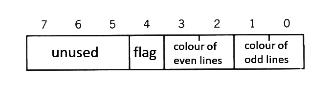
The "border colour" in screen mode 6 has special meanings. Figure 2.2 shows the bitwise meanings of <border colour> in the mode. In this mode, by changing the flag (bit 4), the colour of vertical lines at odd X-coordinates and the colour of those at even coordinates can be specified differently.
When the flag is 0 (the value of border colour is one of the values from 0 to 15), different colours cannot be specified and the border colour is set as the colour of vertical odd lines. When the flag is 1 (the value of border colour is one of the values from 16 to 31), the border colours are set as the colour of vertical odd lines and that of vertical even lines; when these two colours are different, the screen shows a vertically-striped pattern.
Figure 2.2 Bitwise meanings for the border colour on screen mode 6
COLOR = (<palette number>, <red brightness>, <green brightness>, <blue brightness>)
This statement sets the colour of the specified palette. See Table 2.4 for the specification of <palette number>. Note that nothing happens and no error occurs wwhen the screen mode is 8, which has no palette feature. Though palette number 0 is ordinally fixed to a transparent colour (that is, border space is seen transparently), it can be dealt in the same way as other palettes by changing the register of VDP:
    VDP(9)=VDP(9) OR &H20        (when dealing as with other palettes)
    VDP(9)=VDP(9) AND &HDF       (when fixing it to a transparent colour)
Table 2.4 Colour specifications for the screen mode.
--------------------------------------------------------
| Screen mode | Colour specification | Range of number |
|-------------+----------------------+-----------------|
|  SCREEN 0   |    Palette number    |     0 to 15     |
|  SCREEN 1   |    Palette number    |     0 to 15     |
|  SCREEN 2   |    Palette number    |     0 to 15     |
|  SCREEN 3   |    Palette number    |     0 to 15     |
|  SCREEN 4   |    Palette number    |     0 to 15     |
|  SCREEN 5   |    Palette number    |     0 to 15     |
|  SCREEN 6   |    Palette number    |     0 to 3      |
|  SCREEN 7   |    Palette number    |     0 to 15     |
|  SCREEN 8   |    Colour number     |     0 to 255    |
--------------------------------------------------------
Brightness of each colour can be set to one of eight steps from 0 to 7 and combinig them enables to display 512 colours; 8 (red) x 8 (green) x 8 (blue).
COLOR=RESTORE
This statement resets the colour palette register according to the contents of the colour palette storage table (see APPENDIX VRAM MAP). For example, if image data written under unusual colour palette settings is BSAVEd, the original images cannot be reproduced because BLOADing the data does not change the colour palettes. Therefore, the image data should be BSAVEd with the colour palette storage table. To obtain the colours of the original images, BLOAD the data and reset the palettes with the COLOR=RESTORE instruction.
COLOR [=NEW]
This statement initialises the colour palette to the same state as when the power of the computer is turned on (see Table 2.5). It is a good idea to place this statement at the beginning and the end of the program.
Table 2.5 Initial colours of colour palettes and palette setting values
------------------------------------------------------------------
| Palette |    Colour     | Brightness | Brightness | Brightness |
| number  |               |  of red    |   of blue  |  of green  |
|---------+---------------+------------+------------+------------|
|    0    | transparent   |     0      |     0      |     0      |
|    1    | black         |     0      |     0      |     0      |
|    2    | bright green  |     1      |     1      |     6      |
|    3    | light green   |     3      |     3      |     7      |
|    4    | deep blue     |     1      |     7      |     1      |
|    5    | bright blue   |     2      |     7      |     3      |
|    6    | deep red      |     5      |     1      |     1      |
|    7    | light blue    |     2      |     7      |     6      |
|    8    | bright red    |     7      |     1      |     1      |
|    9    | light red     |     7      |     3      |     3      |
|   10    | bright yellow |     6      |     1      |     6      |
|   11    | pale yellow   |     6      |     3      |     6      |
|   12    | deep green    |     1      |     1      |     4      |
|   13    | purple        |     6      |     5      |     2      |
|   14    | grey          |     5      |     5      |     5      |
|   15    | white         |     7      |     7      |     7      |
------------------------------------------------------------------
2.3 Additions or Modifications for the Character Display
LOCATE [<X-coordinate>[, <Y-coordinate>[, <cursor switch>]]]
This statement specifies the location to display a character in the text display screen.
Since an 80-character display feature has been added to the screen mode 0, the X-coordinate value can be specified up to 79.
2.4 Additions or Modifications for the Graphics Display
LINE [{(X1,Y1) | STEP(X1,Y1)}] - {(X2,Y2) | STEP(X2,Y2)}[, <colour> [, {B|BF}[, <logical operation>]]]PSET {(X,Y) | STEP(X,Y)}[, <colour>[, <logical operation>]]PRESET {(X,Y) | STEP(X,Y)}[, <colour>[, <logical operation>]]
The specifiable coordinate range of these statements varies according to the screen mode (see Table 2.6).
Table 2.6 Range of coordinates for each screen mode
-------------------------------------------------
| Screen mode |  X-coordinate  |  Y-coordinate  |
|-------------+----------------+----------------|
|  SCREEN 2   |    0 to 255    |    0 to 191    |
|  SCREEN 3   |    0 to 255    |    0 to 191    |
|  SCREEN 4   |    0 to 255    |    0 to 191    |
|  SCREEN 5   |    0 to 255    |    0 to 211    |
|  SCREEN 6   |    0 to 511    |    0 to 211    |
|  SCREEN 7   |    0 to 511    |    0 to 211    |
|  SCREEN 8   |    0 to 255    |    0 to 211    |
-------------------------------------------------
The logical operation feature is new. When <logical operation> is specified, a logical operation is done between the specified <colour> and the original colour, and the colour of its result will be used to draw. Logical operation types are listed in Table 2.7. <Colour> is specified by the palette number, except for screen mode 8.
Table 2.7 Logical operation
-----------------------------------------------------------------------------
|    Logical operation    |               Function to draw                  |
|-------------------------+-------------------------------------------------|
| PSET (default) ,TPSET   | Use "specified colour"                          |
| PRESET         ,TPRESET | Use "NOT (specified colour)"                    |
| XOR            ,TXOR    | Use "(background colour) XOR (specified colour)"|
| OR             ,TOR     | Use "(background colour) OR (specified colour)" |
| AND            ,AND     | Use "(background colour) AND (specified colour)"|
-----------------------------------------------------------------------------
Note: The list above assumes that <colour> is (specified colour) and that the original colour of the place to be drawn is (background colour). Specifying a logical operation preceded by "T" causes nothing to be done when <colour> is transparent (colour 0).
CIRCLE {(X,Y) | STEP(X,Y)},<radius>[, <colour>[, <start angle>[, <end angle>[, <proportion>]]]]
The coordinate range to be specified depends on the screen mode (see Table 2.6). <colour> is specified by the palette number, except for screen mode 8.
PAINT {(X,Y) | STEP(X,Y)}[, <colour>[, <border colour>]]
The coordinate range to be specified depends on the screen mode (see Table 2.6). <Colour> is specified by the palette number, except for screen mode 8. The specification of <border color> is invalid in screen modes 2 and 4.
2.5 Additions or modifications for VDP access
BASE (<expression>)
This system variable contains the starting address of each table assigned to VRAM. The contents of <expression> and the screen mode tables correspond as listed in Table 2.8.
The starting address of the table can be read for each <expression>, but can be written only when <expression> is a value from 0 to 19 (that is, from screen mode 0 to screen mode 3).
Note that the table of screen mode 4 changes as you change the table address of screen mode 2.
Address returned for screen mode from 5 to 8 is the offset value from the starting address of the active page.
Table 2.8 Correspondences between BASE set values and VRAM table
------------------------------------------------------
| Expression | Screen mode |         Table           |
|------------+-------------+-------------------------|
|     0      |      0      | Pattern name table      |
|     1      |      0      | N/A                     |
|     2      |      0      | Pattern generator table |
|     3      |      0      | N/A                     |
|     4      |      0      | N/A                     |
|     5      |      1      | Pattern name table      |
|     6      |      1      | Colour table            |
|     7      |      1      | Pattern generator table |
|     8      |      1      | Sprite attribute table  |
|     9      |      1      | Sprite generator table  |
|    10      |      2      | Pattern name table      |
|    11      |      2      | Colour table            |
|    12      |      2      | Pattern generator table |
|     .      |      .      |            .            |
      .             .                   .
      .             .                   .
|            |             |                         |
|    43      |      8      | Sprite attribute table  |
|    44      |      8      | Sprite generator table  |
------------------------------------------------------
VDP (<n>)
This allows the value of VDP register to be read and written. <n> is slightly different from the actual VDP register number. Their correspondances are listed in Table 2.9.
Table 2.9 Correspondances with VDP register
---------------------------------------------------
|    n     |  VDP register number   | Access mode |
|----------+------------------------+-------------|
|  0 to 7  | 0 to 7 (same as MSX1)  | Read/write  |
|    8     |   Status register 0    | Read only   |
|  9 to 24 |        8 to 23         | Read/write  |
| 33 to 47 |       32 to 46         | Write only  |
| -1 to -9 | Status register 1 to 9 | Read only   |
---------------------------------------------------
VPEEK (<address>)VPOKE <address>, <data>
When the screen mode is from 5 to 8, the offset value from the starting address of the active page should be set for <address>. Valid range for the <address> value is from 0 to 65535 and the valid range for the data value is from 0 to 255.
BSAVE <filename>, <start address>, <end address>, SBLOAD <filename> ,S
These are statements of DISK BASIC, used to save/load the contents of VRAM to/from disk files. Both can be used in any screen mode, note, however, that only the active pages are valid when the screen mode is from 5 to 8. No cassette tapes can be used. Valid value range of <address> is from -32768 to -2, or from 0 to 65534 (&HFFFE).
COPY (X1,Y1) - (X2,Y2)[, <source page>] TO (X3,Y3)[, <destination page> [, <logical operation>]]COPY (X1,Y1) - (X2,Y2)[, <source page>] TO {<array variable name> | <filename>}COPY {<array variable name> | <filename>}[, <direction>] TO (X3,Y3)[, <destination page>[, <logical operation>]]COPY <filename> TO <array variable name>COPY <array variable name> TO <filename>
The COPY statements transfer screen data and are valid when the screen mode is from 5 to 8. VRAM, array variables, and disk files can be used with these statements, and data can be transferred among these at will.
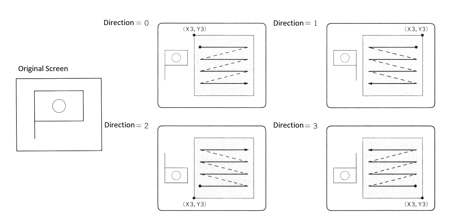
(X1,Y1) - (X2,Y2) means that the rectangular area, with a diagonal formed by these two coordinates is to be transferred. <Source page> and <destination page> indicate the page to be transferred from and the page to be transferred to, respectively, and if these pages are omitted, the active pages are assumed. <Direction> indicates the direction for writing the screen data to the screen, and is specified by a number from 0 to 3 (see Figure 2.3).
Figure 2.3 Directions for writing the screen data
<Array variable> is of the integer type, or single precision real type, or double precision real type. It should be prepared with enough area to get the screen data. Its size can be calculated by Expression 1 as shown below. <Pixel size> is the number of bits to be used to express one dot on the screen. It is 4 when the screen mode is 5 or 7, 2 for mode 6, and 8 for mode 8. Screen data is stored in the format shown in Figure 2.4.
Expression 1
INT ((<pixel size>*(ABS(X2-X1)+1)*(ABS(Y2-Y1)+1)+7)/8)+4 bytes
Figure 2.4 Screen data format
------------------------------------
| horizontal width low-order byte  | 0
|----------------------------------|
| horizontal width high-order byte | 1
|----------------------------------|
| vertical height low-order byte   | 2
|----------------------------------|
| vertical height high-order byte  | 3
|----------------------------------|
|                                  | 4
|                                  | .
|      screen data (*)             | .
|                                  | .
|                                  | n bytes
------------------------------------

(*) If the length of data cannot be divided by byte, excess bits are to be 0.
<Logical operation> specifies a logical operation between the data which resides on the destination and the data to be transferred. See Table 2.7 for the parameters to specify.
When operations preceded by "T" are specified, the transparent portions of the source will not be transferred.
2.7 Additions or Modifications for Sprite
The sprites used in screen mode 4-8 of MSX2 are called sprite mode 2, which has upgraded a great deal as compared with MSX1. On MSX1, for example, one sprite could treat only one colour, while in this mode of MSX2 different colours can be specified for each horizontal line and so multi-coloured characters can be realised with one sprite. Additionally, it is a good idea to combine two sprites as though they were one sprite to paint each dot with different colours. And, on MSX1, when more than five sprites are arrayed on a horizontal line, the sprites after the fifth one were not displayed, but on MSX2 up to eight sprites can be displayed, so a higher flexibility is offered.
Colours which can be specified for sprites are shown in Table 2.4 (colour statement) except for screen mode 8. The sprite in screen mode 8, not capable of using the palette, uses the colour number for the specification, and only 16 colours can be used (see Table 2.10).
Table 2.10 Sprite colours in screen mode 8
-------------------------------------------------------------------------
| 0: Black        | 1: Deep Blue    | 2: Deep Red     | 3: Deep Purple  |
|-----------------+-----------------+-----------------+-----------------|
| 4: Deep Green   | 5: Turquoise    | 6: Olive        | 7: Grey         |
|-----------------+-----------------+-----------------+-----------------|
| 8: Light Orange | 9: Blue         | 10: Red         | 11: Purple      |
|-----------------+-----------------+-----------------+-----------------|
| 12: Green       | 13: Light Blue  | 14: Yellow      | 15: White       |
-------------------------------------------------------------------------
PUT SPRITE <sprite plane number>[, {(X,Y) | STEP(X,Y)}[, <colour>[, <sprite pattern number>]]]
In screen modes 1 through 3, Y-coordinate was 209 for erasing the display of the specified sprite and was 208 for erasing the displays of the specified sprite and all sprites following it, but in screen modes 4 through 8, where the limit of Y-coordinate has been increased to 212 dots, the values to be specified are now 217 and 216, respectively.
COLOR SPRITE$ (<sprite plane number>) = <string expression>
This statement specifies a colour for each horizontal line (see Figure 2.5).
<String expression> consists of one to sixteen characters. Bits 0 throgh 3 of the character's ASCII code are used for the colour specification, and bits 4 throgh 7 are used to specify each function of the sprite (see Table 2.11). These specifications are valid only for screen modes 4 through 8.
COLOR SPRITE$ = CHR$ (colour of the first line) + CHR$ (colour of the second line) + ...... + CHR$ (colour of the eight line)
Figure 2.5 Relation of the sprite and <string expression>
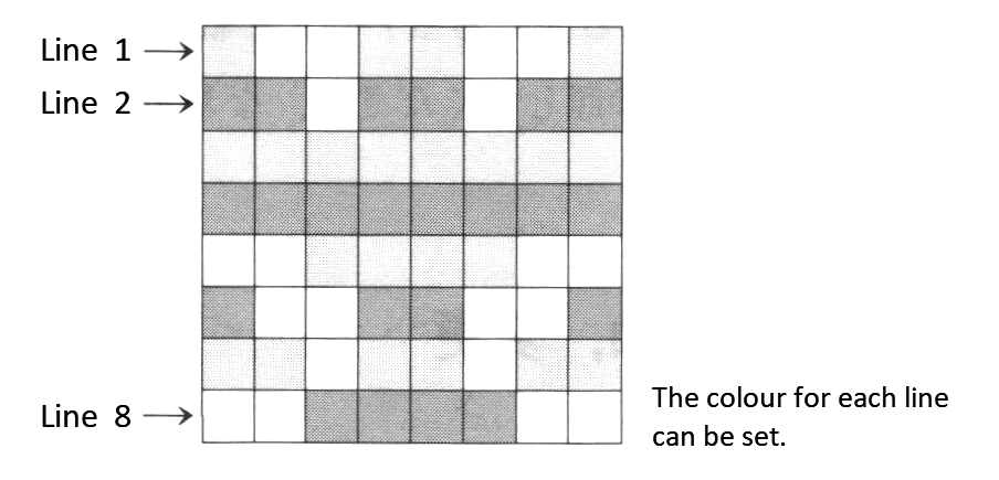
Table 2.11 Bitwise meanings of string expression
-------------------------------------------------------------------------
|    b7    | If 1, move the sprite to left by 32 dots.                  |
|----------+------------------------------------------------------------|
|          | If 1, move the sprites of the successive planes together.  |
|    b6    | The priority and conflict of sprites are ignored, and when |
|          | sprites are piled up, they are displayed in the colour     |
|          | which is OR-ed with their colour numbers. *                |
|----------+------------------------------------------------------------|
|    b5    | If 1, the conflict of sprites are ignored.                 |
|----------+------------------------------------------------------------|
|    b4    | Unused.                                                    |
|----------+------------------------------------------------------------|
| b0 to b3 | Palette number.                                            |
-------------------------------------------------------------------------
-
For example, assuming that bit 6 of sprite plane 1 is "0" and bit 6 of sprite plane 2 is "1", only by moving sprite plane 1, will sprite plane 2 be displayed displayed to be piled at the same location.
-
COLOR SPRITE (<sprite plane number>) = <expression>
This statement sets the whole sprite of the specified plane to the <expression>, this uses <expression> for colour specification. The format of the colour specification is the same as shown in Table 2.11, but the specification for b7 is disabled. These are valid for screen modes 4 through 8.
2.8 Additions for Optional Features
SET VIDEO [<mode>[, <Ym>[, <CB>[, <sync>[, <voice>[, <video input>[, <AV control>]]]]]]]
This statement is for the superimposer or the digitiser which are optional, so it can be used only for machines which have these features.
<Mode> sets the superimposing mode and can be set to the value listed in Table 2.12.
When <Ym> is 1, the brightness of the television is halved.
When <CB> is 1, the colour bus of VDP is prepared for input, and, when 0, it is prepared for output.
When <sync> is 1, "external sync" is selected, and, when 0, "internal sync" is selected.
<Voice> specifies whether to mix external signal for output, and values are listed in Table 2.13.
<Video input> is used to alternate the input of external video signals. When it is 0, the RGB multiconnector is selected; when it is 1, external video signal connector is selected.
<AV control> specifies AV control terminal output of the RGB multiconnector. When it is 0, the output is OFF; when it is 1, the output is ON.
Table 2.12 Input values for SET VIDEO <mode>.
----------------------------------------
| Mode | S1 | S2 | TP | Display screen |
|------+----+----+----+----------------|
|  0   | 0  | 0  | 0  | Computer       |
|  1   | 0  | 1  | 1  | Computer       |
|  2   | 0  | 1  | 0  | Superimpose    |
|  3   | 1  | 0  | 0  | Television     |
----------------------------------------
Note: In the case of mode 0, external sync cannot be used. In other modes the compoalte output of VDP is not available. S1, S0, and TP are the names of flags in the VDP register.
Table 2.13 Input values for SET VIDEO <voice>
----------------------------------------------
| Voice | Function for external voice signal |
|-------+------------------------------------|
|   0   | No mixing                          |
|   1   | Right channel mixed                |
|   2   | Left channel mixed                 |
|   3   | Both channels mixed                |
----------------------------------------------
COPY SCREEN [<mode>]
This statement is used for writing data from the colour bus to VRAM, for example, after digitising. This is valid for screen modes 5 to 8.
In mode 0, one field of signals is digitised and written to the display page; in mode 1, two successive fields (that is, one frame) of signals are written to (display page - 1)th page and the display page, so the display page should be an odd page when the mode is 1. The default mode is 0.
2.9 Additions for Timer Features
GET DATE <string variable name> [,A]
This statement is for reading the date from the timer and assigning it to the string variable. The format of date to be read is as follows:
YY/MM/DD (YY = lower two digits of year, MM = month, DD = day)
e.g.) 85/03/23 (March 23, 1985)
When option A is specified, the alarm date is read.
SET DATE <string expression>[, A]
This statement sets date to timer. The form of parameter and option is the same as "GET DATE"
e.g.) SET DATE "85/03/23"
GET TIME <string variable>[, A]
This statement is for reading time from the timer and assigning it to a string variable. The form of time to be read is as follows:
HH:MM:SS (HH = hour, MM = minute, SS = second)
e.g.) 22:15:00 (22 hours 15 minutes 0 seconds)
When A is specified, the time for the alarm is read.
SET TIME <string expression>[, A]
This statement sets the time to the timer. The form of parameter and option is the same as "GET TIME".
e.g.) SET TIME "22:15:00"
- The Alarm
Since the alarm feature is optional, the action taken at the specified time depends on the machine (ordinarily nothing happens).
When the alarm is to be set in both "SET DATE" and "SET TIME", "SET TIME" should be done first (when "SET TIME" is done, date of the alarm set by "SET DATE" will be erased).
The minimum setting for alarm is in minutes (setting in seconds is ignored).
2.10 Additions for Memory Switch
Using "SET" instructions, various settings described below can be stored to the battery-powered RAM in CLOCK-IC. Settings based on these are done automatically at system startup (when the system is powered or reset). "SET TITLE", "SET PROMPT", and "SET PASSWORD" use the same RAM, so only the most recent instruction is valid.
SET ADJUST (<X-coordinate offset>, <Y-coordinate offset>)
This statement sets the location to display on the screen. The coordinate offset is from -7 to 8.
SET BEEP <timbre>, <volume>
This statement sets BEEP sound. <Timbre> and <volume> are from 1 to 4.
Table 2.14 shows the correspondance of <timbre> and to the actual sound.
Table 2.14 Input values for of SET BEEP
------------------------------------------
| Timbre |            Sound              |
|--------+-------------------------------|
|   1    | High tone beep (same as MSX1) |
|   2    | Low tone beep                 |
|   3    | 2 - tone beep                 |
|   4    | 3 - tone beep                 |
------------------------------------------
SET TITLE <string expression>[, <title colour>]
This statement specifies the title and the colour of the initial screen at system startup. <Title> is set by a string of up to 6 characters and <colour> is one of the values on Table 2.15. When <title> is 6 characters, keyboard input is awaited just after the title screen is displayed.
Table 2.15 Available colours in SET TITLE
-----------------------------------------------------
| Color         |   1    |   2    |   3    |   4    |
|---------------+--------+--------+--------+--------|
| Screen color  | Blue   | Green  | Red    | Orange |
-----------------------------------------------------
SET PROMPT <prompt>
This statement sets the prompt. <Prompt> can have up to 6 characters.
SET PASSWORD <password>
This statement sets a system password. <Password> is a string expression up to 255 characters. Once this statement is done, input of the password is requested for invoking the system. When the correct password is given, the system is normally invoked; otherwise, correct password input is requested. When the system is invoked by pressing both graphic key and stop key, no password input is requested (in this case, the password setting has been done by the key cartridge; however, password input is always required for system startup). The password is disabled by specifying a null character in SET TITLE.
SET SCREEN
This statement records the current parameters of the "SCREEN" statement. At the system startup, they are automatically set. Items to be recorded are the following:
Screen number of text mode                      Key click switch
Screen width of text mode                       Printer option
Foreground, background, and border colours      Cassette baud rate
Function key switch                             Display mode
2.11 Additions for RAM Disk
On MSX1 RAM from 0000H to 7FFFH was used only by DOS. On MSX2, however, this portion can be used as a RAM disk of up to 32K bytes. The format of the file name for RAM disk is described below, where <filename> is a string which consists of 1 to 8 characters and <extension> is one which consists of 1 to 3 characters. Note that ";" (colon), "." (period), control characters of character codes 00H-1FH, and graphic symbols consisting of two bytes cannot be used.
MEM: <filename>[.<extension>]
The following are executable operations for the RAM disk:
1. Load/save a BASIC program (always saved in ASCII format)
SAVE, LOAD, RUN, MERGE
When any of the above commands is executed from the program, control returns to the command level.
2. Read/write a sequential file
    OPEN, CLOSE
    PRINT #, PRINT USING #
    INPUT #, LINE INPUT #, INPUT$
    EOF, LOC, LOF
The RAM disk does not support the following instructions:
- Random file Read/Write
- BLOAD, BSAVE
- COPY
CALL MEMINI [(<size>)]
This statement specifies the amount of memory to be used as a RAM disk, initialises the RAM disk, and deletes all files. When the RAM disk is to be used, this statement should always be executed.
<Size> is "the amount of memory to be used as RAM disk minus 1". By default, the maximum size is allocated for RAM disk. "CALL MEMINI(0)" causes the RAM disk feature to be disabled.
CALL MFILES
This statement displays file names on the RAM disk.
CALL MKILL ("<filename>")
This statement deletes the specified file.
CALL MNAME ("<old filename>" AS "<new filename>")
This statement renames the specified file.
2.12 Other Additions
PAD (<expression>)
This function returns status to touch pad (touch panel), light pen, mouse, or track ball.
When <expression> is 0 to 7, it returns the status to touch pad as on MSX1, and, when <expression> is 8 to 11, it returns the status to light pen. Since the coordinates and the value of the switch are read when "PAD(8)" is executed, other data should be read after confirming that the value of PAD(8) is -1 (see Table 2.16).
Table 2.16 <Expression> returning status to light pen
---------------------------------------------------------------------
| Expression |                 The value returned                   |
|------------+------------------------------------------------------|
|      8     | -1 when data of light open is valid; otherwise, 0    |
|      9     | X - coordinate of light pen                          |
|     10     | Y - coordinate of light pen                          |
|     11     | -1 when switch of light pen is pressed; otherwise, 0 |
---------------------------------------------------------------------
This statement returns the status of the mouse or the track ball connected to port 1 when <expression> is 12 to 15 or connected to port 2 when it is 16 to 19 (see Table 2.17). The mouse and track ball are automatically distinguished from each other.
Table 2.17 <Expression> returning status to mouse or track ball
---------------------------------------
| Expression |   The value returned   |
|------------+------------------------|
|   12, 16   | - 1; for input request |
|   13, 17   | X - coordinate         |
|   14, 18   | Y - coordinate         |
|   15, 19   | 0 (unused)             |
---------------------------------------
Coordinate data is read when PAD(12) or PAD(16) is examined. Coordinate data should be obtained after examining these. The STRIG function is used with the joystick to input the status of the trigger button.
3. INTERNAL STRUCTURE OF BASIC
Knowledge of how the BASIC interpreter controls and executes programs is necessary for more advanced use of BASIC. The internal structure of BASIC is discussed next.
3.1 User's Area
The lowest address of the user's area was different in the MSX1 machine whose amount of RAM was 8K, 16K, 32K, or 64K; in MSX2, it is always 8000H, because MSX2 machines have at least 64K of RAM. It can be obtained from the content of BOTTOM (FC48H).
The highest address of the user's area when no disk drives are connected is F380H; when disk drives are connected (using DISK-BASIC), it depends on the number of disk drives or on the disk capacity. It can be obtained from the content of HIMEM (FC4AH) after reset and before executing CLEAR statement.
Figure 2.6 shows the state of memory when MSX is invoked.
Figure 2.6 State of memory for BASIC mode
0000 --------------------
     |                  |
     |      BASIC       |
     |   Interpreter    |
     |                  |
8000 |------------------|  ⟵ (BOTTOM)             --+
     |                  |                            |
     |    User area     |                   --+      |
     |                  |                     |      |
     |------------------|  ⟵ (HIMEM)         |      |32K
     |  Disk work area  |             --+     |16K   |
F380 |------------------|               | 8K  |      |
     | System work area |               |     |      |
FFFF --------------------             --+   --+    --+
Note: Though the machine has more than 32K bytes of RAM, only 32K bytes are used for BASIC. On MSX2, however, another 32K bytes can be used as a RAM disk by BASIC.
When developping a program on MSX2, we recommend you create it at addresses 8000H to DE3FH as if to install a 2DD-2 drive whose highest address of the user's area is the lowest. The work area of the disk can grow even larger, therefore, HIMEM of the application program should be checked to prevent disasters even in the worst situation. The following are ways to prevent this:
- Make the work area relocatable
- Get the work area from BOTTOM
- Stop after instructing to reduce the number of drives
On MSX, even when disks are mounted, they can be cut off by resetting while pressing the SHIFT key. When only one drive is mounted, the normal invocation causes the work area for two drives to be allocated (mainly for 2 drive simulator): in such a case, invoking the works area for only one drive is possible by resetting while pressing the CTRL key. If these steps are taken, more user's area can be allocated.
3.2 Detailed View of the User's Area
Figure 2.7 shows how the user's area will be used in BASIC, and Table 2.18 shows the work area with information about where these areas start. This work area is read-only (the initialising routine sets it when reset), so actions when it is changed are not guaranteed.
Figure 2.7 State of the user's area
BOTTOM -->  ---------------------- The lowest of the user's area
            |                    | (8000H on MSX2)
TXTTAB -->  |--------------------|
            |                 |  |
            |      BASIC      V  |
            |   program area     |
            |                    |
VARTAB -->  |--------------------| Depends on the amount of text
            | Simple variable |  |
            |      area       V  |
ARYTAB -->  |--------------------|
            | Array variable  |  |
            |      area       V  |
STREND -->  |--------------------| Depends on the number of variables
            |                 |  |
            |                 V  |
            |     Free area      |
            |                 ^  |
            |                 |  |
SP     -->  |--------------------| Area pointed by SP register
            | Stack           ^  |
            | area            |  |
STKTOP -->  |--------------------| --+
            | String          ^  |   | Set by 1st parameter of CLEAR
            | area            |  |   |
MEMSIZ -->  |--------------------| --+
            | File            ^  |
            | control block   |  |
HIMEM  -->  |--------------------| Set by 2nd parameter of CLEAR
            |                    |
            | Assembly language  |
            | area               |
            |                    |
            ---------------------- The highest of the user's area
                                   (depends on the presence of disks)
Table 2.18 Work areas with start and end addresses of each area
Area name                  Start address           End address
----------------------------------------------------------------------------
User's area            | [BOTTOM (FC48H)] | ([HIMEM (FC4AH)] when reset) - 1
Program area           | [TXTTAB (F676H)] | [VARTAB (F6C2H)] - 1
Simple variable area   | [VARTAB (F6C2H)] | [ARYTAB (F6C4H)] - 1
Array variable area    | [ARYTAB (F6C4H)] | [STREND (F6C6H)] - 1
Free area              | [STREND (F6C6H)] | [SP register] - 1
Stack area             | [SP register]    | [STKTOP (F674H)] - 1
String area            | [STKTOP (F674H)] | [MEMSIZ (F672H)] - 1
(start of unused area) | [FRETOP (F69BH)] |
File control block     | [MEMSIZ (F672H)] | [HIMEM  (FC4AH)] - 1
Assembly language area | [HIMEM  (FC4AH)] | to the end of the user's area
----------------------------------------------------------------------------
Roles of each user's area are described below.
- BASIC program area
A program written in BASIC is stored from the lowest address (8000H on MSX2) of the user's area and its size depends on the amount of the program.
- Variable area
The variable area is located just after the BASIC program area. It is secured to store the name and the value of the variables used when executing the program. The variables storage formats are shown in Figure 2.8 (simple variables) and Figure 2.9 (array variables). Using array variables without declaring in the DIM statement causes the area to be allocated as an array with ten indexes. However, arrays which are more than four dimensional must be declared.
Figure 2.8 Storage format of simple variables
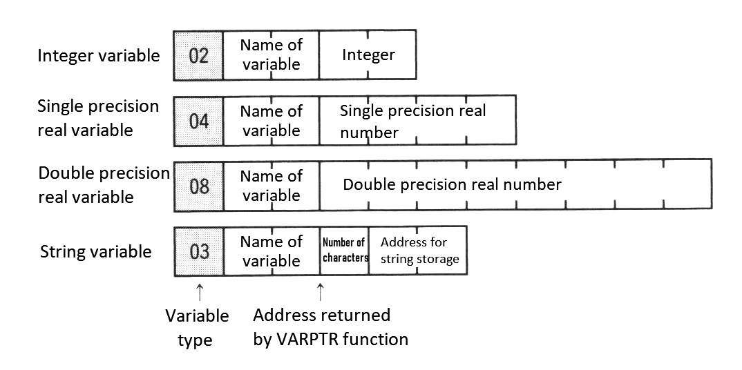
Figure 2.9 Storage format of array variables
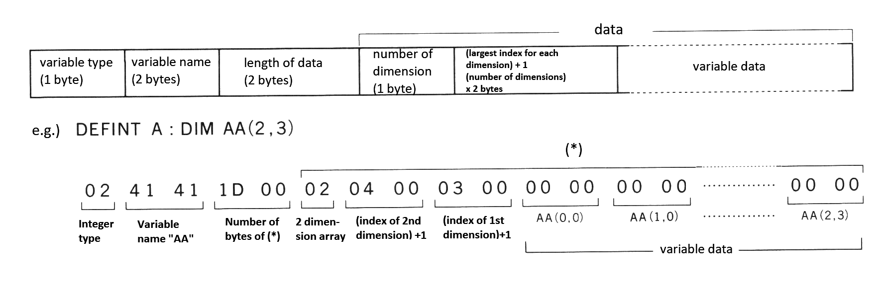
Note: variable data format is the same as the storage format of simple variables. The lower of the 2-byte value is stored first, and the higher byte last.
- Free area
If the program area or the variable area grows too large or a lot of data is stacked and the free area runs out, an "OUT OF MEMORY" error occurs. The amount of free area can be checked by examining PRINT FRE(0) using the FRE function in BASIC.
- Stack area
This is the stack area used by BASIC. It is used in order from high-order address when executing GOSUB or FOR.
- String area
This area is used to reserve the contents of string variables and used from high-order address. The space in this area can be specified by the first parameter of the CLEAR statement in BASIC. The default is 200 bytes. Exhausting the space in this area causes a "OUT OF STRING SPACE" error. The amount of unused area can be checked by examining PRINT FRE("") using the FRE function in BASIC
- File control block
File information is stored in this area with 10BH (267) bytes allocated for each file. The amount of space for files can be specified by the MAXFILES statement of BASIC. At reset, the area for one file (MAXFILES = 1) is allocated. Another space is always allocated for SAVE and LOAD instructions, so actually area for two files is allocated. Table 2.19 shows the format of file control block.
Table 2.19 File control block (FCB) format
  Offset    Label                    Meaning
--------------------------------------------------------------
| + 0   |   FL.MOD   |   Mode of the file opened             |
| + 1   |   FL.FCA   |   Pointer (low) to FCB for BDOS       |
| + 2   |   FL.LCA   |   Pointer (high) to FCB for BDOS      |
| + 3   |   FL.LSA   |   Backup character                    |
| + 4   |   FL.DSK   |   Device number                       |
| + 5   |   FL.SLB   |   Internal use for the interpreter    |
| + 6   |   FL.BPS   |   FL.BUF location                     |
| + 7   |   FL.FLG   |   Flag containing various information |
| + 8   |   FL.OPS   |   Virtual head information            |
| + 9...|   FL.BUF   |   File buffer (256 bytes)             |
--------------------------------------------------------------
- Assembly language area
Use this area to write programs in assembly language or to operate from memory directly. To do these, this area should be reserved by CLEAR statement.
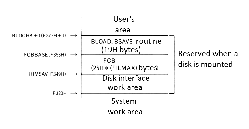
- Work area for disk
Figure 2.10 shows the work area allocated when a disk is mounted. Note that this area does not exist when no disk is mounted. Labels to the right of this figure shows the address information which resides there.
Figure 2.10 Work area for disk
3.3 Storage format of BASIC programs
Programs are stored in memory as shown in Figure 2.11 and the meaning of its contents are described below.
Figure 2.11 Text storage format
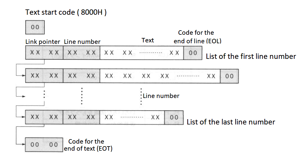
Note: Link pointers and line numbers are stored with their low bytes first and high bytes last.
- Link pointer
The text pointer to the next line is given in the form of an absolute address.
- Line number
This stores the line number of the program, normally the values from 0 to 65529 (from 0000H to FFF9H). It is possible to make line numbers of 65530 or more, but LIST command does not list them.
- Text
The program body is stored here in the intermediate code format. Reserved words (keywords), operators, numeric values are converted to the intermediate codes, and others (such as variable names or string constantes) are stored as character codes. Table 2.20 lists the intermediate codes and Figure 2.12 shows the numeric formats in text.
See the appendix at the end of this book for character codes. Graphic characters are stored in 2 bytes (2 characters) of "CHR$(1) + (graphic character code + 64)", so be careful when defining graphic characters.
Table 2.20 List of intermediate codes
-------------------   -------------------   -------------------
| >       |    EE |   | ERR     |    E2 |   | PAINT   |    BF |
| =       |    EF |   | ERROR   |    A6 |   | PDL     | FF A4 |
| <       |    F0 |   | EXP     | FF 8B |   | PEEK    | FF 97 |
| +       |    F1 |   | FIELD   |    B1 |   | PLAY    |    C1 |
| -       |    F2 |   | FILES   |    B7 |   | POINT   |    ED |
| *       |    F3 |   | FIX     | FF A1 |   | POKE    |    98 |
| /       |    F4 |   | FN      |    DE |   | POS     | FF 91 |
| ^       |    F5 |   | FOR     |    82 |   | PRESET  |    C3 |
| \       |    FC |   | FPOS    | FF A7 |   | PRINT   |    91 |
| ABS     | FF 86 |   | FRE     | FF 8F |   | PSET    |    C2 |
| AND     |    F6 |   | GET     |    B2 |   | PUT     |    B3 |
| ASC     | FF 95 |   | GOSUB   |    8D |   | READ    |    87 |
| ATN     | FF 8E |   | GOTO    |    89 |   | REM     | 3A 8F |
| ATTR$   |    E9 |   | HEX$    | FF 9B |   | RENUM   |    AA |
| AUTO    |    A9 |   | IF      |    8B |   | RESTORE |    8C |
| BASE    |    C9 |   | IMP     |    FA |   | RESUME  |    A7 |
| BEEP    |    C0 |   | INKEY$  |    EC |   | RETURN  |    8E |
| BIN$    | FF 9D |   | INP     | FF 90 |   | RIGHT$  | FF 82 |
| BLOAD   |    CF |   | INPUT   |    85 |   | RND     | FF 88 |
| BSAVE   |    D0 |   | INSTR   |    E5 |   | RSET    |    B9 |
| CALL    |    CA |   | INT     | FF 85 |   | RUN     |    8A |
| CDBL    | FF A0 |   | IPL     |    D5 |   | SAVE    |    BA |
| CHR$    | FF 96 |   | KEY     |    CC |   | SCREEN  |    C5 |
| CINT    | FF 9E |   | KILL    |    D4 |   | SET     |    D2 |
| CIRCLE  |    BC |   | LEFT$   | FF 81 |   | SGN     | FF 84 |
| CLEAR   |    92 |   | LEN     | FF 92 |   | SIN     | FF 89 |
| CLOAD   |    9B |   | LET     |    88 |   | SOUND   |    C4 |
| CLOSE   |    B4 |   | LFILES  |    BB |   | SPACE$  | FF 99 |
| CLS     |    9F |   | LINE    |    AF |   | SPC(    |    DF |
| CMD     |    D7 |   | LIST    |    93 |   | SPRITE  |    C7 |
| COLOR   |    BD |   | LLIST   |    9E |   | SQR     | FF 87 |
| CONT    |    99 |   | LOAD    |    B5 |   | STEP    |    DC |
| COPY    |    D6 |   | LOC     | FF AC |   | STICK   | FF A2 |
| COS     | FF 8C |   | LOCATE  |    D8 |   | STOP    |    90 |
| CSAVE   |    9A |   | LOF     | FF AD |   | STR$    | FF 93 |
| CSNG    | FF 9F |   | LOG     | FF 8A |   | STRIG   | FF A3 |
| CSRLIN  |    E8 |   | LPOS    | FF 9C |   | STRING$ |    E3 |
| CVD     | FF AA |   | LPRINT  |    9D |   | SWAP    |    A4 |
| CVI     | FF A8 |   | LSET    |    B8 |   | TAB(    |    DB |
| CVS     | FF A9 |   | MAX     |    CD |   | TAN     | FF 8D |
| DATA    |    84 |   | MERGE   |    B6 |   | THEN    |    DA |
| DEF     |    97 |   | MID$    | FF 83 |   | TIME    |    CB |
| DEFDBL  |    AE |   | MKD$    | FF B0 |   | TO      |    D9 |
| DEFINT  |    AC |   | MKI$    | FF AE |   | TROFF   |    A3 |
| DEFSNG  |    AD |   | MKS$    | FF AF |   | TRON    |    A2 |
| DEFSTR  |    AB |   | MOD     |    FB |   | USING   |    E4 |
| DELETE  |    A8 |   | MOTOR   |    CE |   | USR     |    DD |
| DIM     |    86 |   | NAME    |    D3 |   | VAL     | FF 94 |
| DRAW    |    BE |   | NEW     |    94 |   | VARPTR  |    E7 |
| DSKF    | FF A6 |   | NEXT    |    83 |   | VDP     |    C8 |
| DSKI$   |    EA |   | NOT     |    E0 |   | VPEEK   | FF 98 |
| DSKO$   |    D1 |   | OCT$    | FF 9A |   | VPOKE   |    C6 |
| ELSE    | 3A A1 |   | OFF     |    EB |   | WAIT    |    96 |
| END     |    81 |   | ON      |    95 |   | WIDTH   |    A0 |
| EOF     | FF AB |   | OPEN    |    B0 |   | XOR     |    F8 |
| EQV     |    F9 |   | OR      |    F7 |   -------------------
| ERASE   |    A5 |   | OUT     |    9C |
| ERL     |    E1 |   | PAD     | FF A5 |
-------------------   -------------------
Figure 2.12 Numeral formats in text
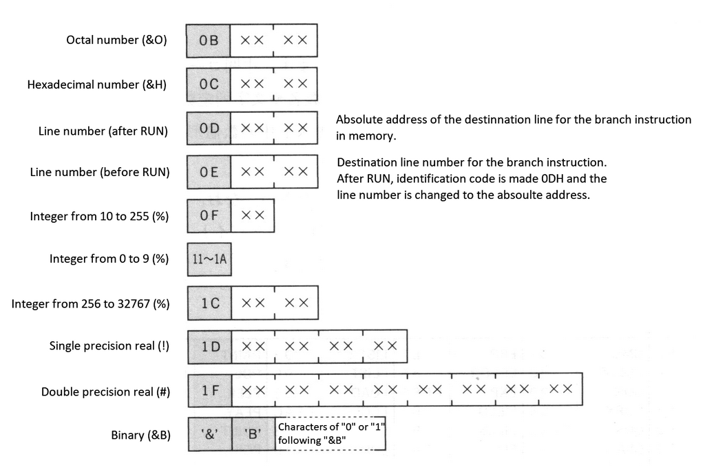
Numbers called "identification codes" are assigned numeric values to distinguish them from reserved words and variable names, and by referring to them the following values can be recognised.
The high and low bytes of a 2-byte numeric value are stored in reverse. Signed numeric values have only the intermediate codes + or - preceding the identifying codes, numeral values themselves are always stored as positive values. Floating-point notations are almost the same as the descriptions of Math-Pack (Mathematical Package) in the APPENDIX, note that numerical values are always stored as positive. Binary numbers (&B) do not have identifying codes and are stored as ASCII codes.
4. LINKING WITH ASSEMBLY LANGUAGE PROGRAMS
As described so far, MSX BASIC version 2.0 has powerful features, but, if you wish to save execution time even more or to make full use of MSX2 hardware, you should use assembly language. The following sections show how to call assembly language programs from BASIC and gives the information you will need.
4.1 USR Function
To call the assembly language routine from BASIC, follow the steps described below. The value in parenthesis of the USR function is passed to the assembly language routine as an argument. The argument may be either an expression or a string expression.
- Specify the starting address of the assembly language program for the execution, using DEF USR statement.
- Call the assembly language program by USR function.
- Execute RET (C9H) when returning from the assembly language routine to BASIC.
e.g.) To call the assembly language program whose starting address is C000H:
    DEFUSR=&HC000
    A=USR(0)
4.2 Data Exchange by the Argument and Return Value of USR Function
When the argument is passed from BASIC to the assembly language program, its type can be checked by examining the contents of register A in the assembly language program (see Table 2.21). Since the object value is stored in the form as shown in Figure 2.13 according to the argument type, you can get the value according to the format. As an example, List 2.1 shows a program which receives an argument of the string type.
Table 2.21 Argument types assigned to register A
--------------------------------------
|  2  |  2-byte integer type         |
|  3  |  String type                 |
|  4  |  Single precision real type  |
|  8  |  Double precision real type  |
--------------------------------------
Figure 2.13 How values are passed as arguments
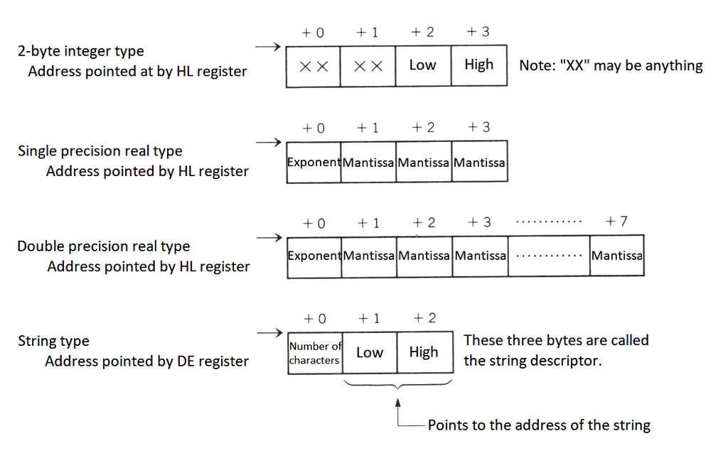
List 2.1 Example of the argument of string type
;************************************************************
;  List 2.1    print string with USR function
;              to use, do  DEF USR=&HB000 : A$=USR("STRING")
;************************************************************
;
CHPUT   EQU     00A2H           ;character output

        ORG     0B000H

RDARG:  CP      3
        RET     NZ              ;parameter is not string

        PUSH    DE
        POP     IX              ;IX := string descriptor
        LD      A,(IX+0)        ;get string length
        LD      L,(IX+1)        ;get string pointer (low)
        LD      H,(IX+2)        ;get string pointer (high)
        OR      A
        RET     Z               ;if length = 0

RD1:    PUSH    AF
        LD      A,(HL)          ;get a characetr
        CALL    CHPUT           ;put a character
        POP     AF
        DEC     A
        RET     Z
        INC     HL
        JR      RD1

        END
On the other hand, these values passed as arguments can be passed to BASIC as USR function values by changing them in the assembly language program. In this case the type of return value can alse be changed to types other that of the argument from BASIC by changing VALTYP (F663H). Note that the amount of characters for a string cannot be changed.
4.3 Making New Commands
In MSX the reserved words "CMD" and "IPL" are currently unused and by changing the pointers to these words (FE0DH and FE03H) to jump to your own assembly language routine, new commands can be built. List 2.2 shows a simple example.
List 2.2 Making CMD command
;*****************************************************************
;  List 2.2   make CMD command ( turn on/off the CAPS LOCK )
; to initialize command:                DEF USR=&HB000 : A=USR(0)
; to use command:                       CMD
;*****************************************************************
;
CHGCAP  EQU     0132H           ;CAPS LAMP on/off
CAPST   EQU     0FCABH          ;CAPS LOCK status
HCMD    EQU     0FE9DH          ;CMD HOOK

        ORG     0B000H

;----- CMD initialize -----   Note:  Executing this section adds the CMD command

        LD      BC,5            ;NEW HOOK SET
        LD      DE,HCMD
        LD      HL,HDAT
        LDIR
        RET

;----- new HOOK data -----    Note:  5-byte data to be written into hook (FE0DH)

HDAT:   POP     AF
        JP      CAPKEY
        NOP

;----- executed by CMD -----  Note:  Actual CMD command

CAPKEY: CALL    CHGCAP
        LD      A,(CAPST)
        CPL
        LD      (CAPST),A
        RET

        END
The first "POP AF" written to the pointer in this case, discards the error handling addresses stacked at "CMD" execution. Without this, the "RET" command would jump to the error handling routine isntead of returning to BASIC. It is a way to use this address for printing errors inside of user routine.
These pointers are reserved for future expansion, so should not be used with application programs on the market.
4.4 Expansion of CMD command
For more sophisticated expansions of statements it is useful if arguments can be passed to the CMD command. As the HL register points to the next location after "CMD" in the BASIC text when the assembly language routine is called, it can be done by appreciating the successive string. The following is a list of internal routines, useful for these.
CHRGTR (4666H/MAIN)
Extract one character from text (see Figure 2.14)
- Input: HL ⟵ Address pointing to text
- Output:
- HL ⟵ Address of the extracted character
- A ⟵ Extracted character
- Z flag ⟵ ON at the end of line (: or 00H)
- CY flag ⟵ ON if 0 to 9
Purpose: Extract one character from the text at (HL + 1). Spaces are skipped.
Figure 2.14 Input/output state of CHRGTR
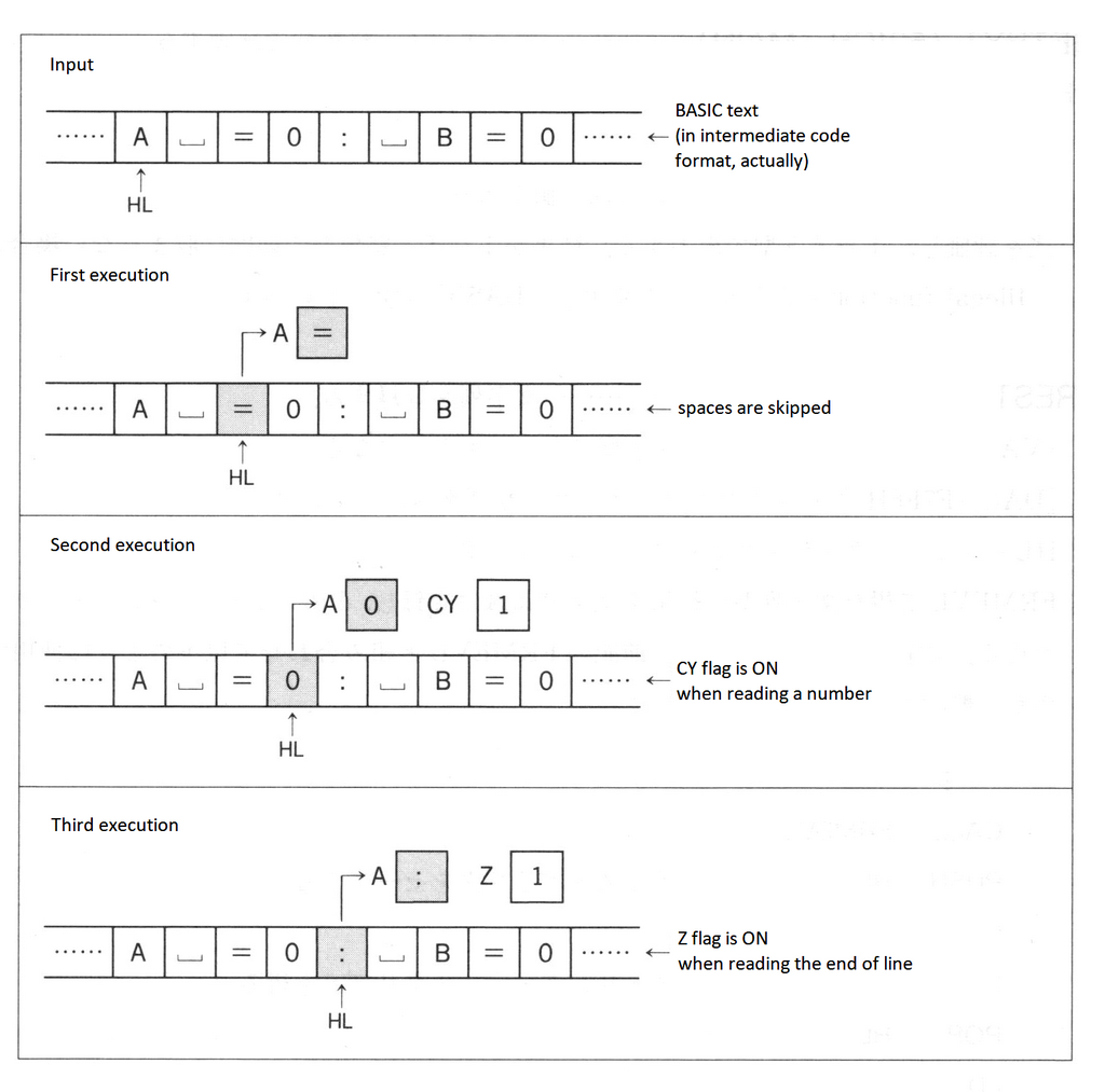
FRMEVL (4C64/MAIN)
Evaluate an expression in text (see Figure 2.15)
- Input: HL ⟵ Starting address of the expression in text
- Output:
- HL ⟵ Address after the expression
- [VALTYP (F663H)] ⟵ Value 2, 3, 4 or 8 according to the expression
- [DAC (F7F6H)] ⟵ Result of the evaluation of the expression
Purpose: Evaluate an expression and make output according to its type.
Figure 2.15 Input/output state of FRMEVL
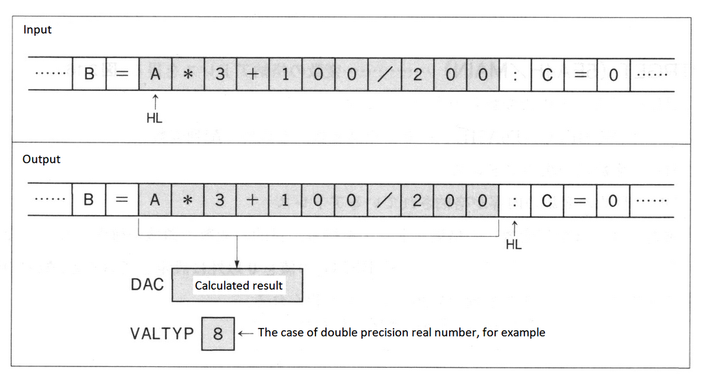
FRMQNT (542F/MAIN)
Evaluate an expression in 2-byte integer type.
- Input: HL ⟵ Starting address of the expression in text
- Output:
- HL ⟵ Address after the expression
- DE ⟵ Result of evaluation of the expression
Purpose: Evaluate an expression and make output in integer type (INT). When the result is beyond the range of 2-byte integer type, an "Overflow" error occurs and the system returns to the BASIC command level.
GETBYT (521C/MAIN)
Evaluate an expression in 1-byte integer type.
- Input: HL ⟵ Starting address of the expression in text
- Output:
- HL ⟵ Next address of expression
- A, E ⟵ Result of expression evaluation (A and E contains the same value.)
Purpose: Evaluate an expression and make 1-byte integer output. When the result is beyond the range of 1-byte integer type, an "Illegal function call" error occurs and the execution returns to BASIC command level.
FRESTR (67D0/MAIN)
Register a string.
- Input:
- [VALTYP (F663H)] ⟵ Type (if not string type, an error occurs)
- [DAC (F7F6H)] ⟵ Pointer to string descriptor
- Output: HL ⟵ Pointer to string descriptor
Purpose: Register the result of the string type obtained by FRMEVL and obtain its string descriptor. When evaluating a string, this is generally combined with FRMEVL described above to use as follows:
 .
 .
 .
CALL    FRMEVL
PUSH    HL
CALL    FRESTR
EX      DE,HL
POP     HL
LD      A,(DE)
 .
 .
 .
PTRGET (5EA4/MAIN)
Obtain the address for the storage of a variable (see Figure 2.16).
- Input:
- HL ⟵ Starting address of the variable name in text
- [SUBFLG (F6A5H)] ⟵ 0: Simple variable, other than 0: array variable
- Output:
- HL ⟵ Address after the variable name
- DE ⟵ Address where the contents of the objective variable is stored
Purpose: Obtain the address for the storage of a variable (or an array variable). Allocation of the area is also done when the area for the objective variable has not been allocated. When the value of SUBFLG is set to other than 0, the starting address of the array is obtained, other than individual elements of the array.
Figure 2.16 Input/output state of PTRGET
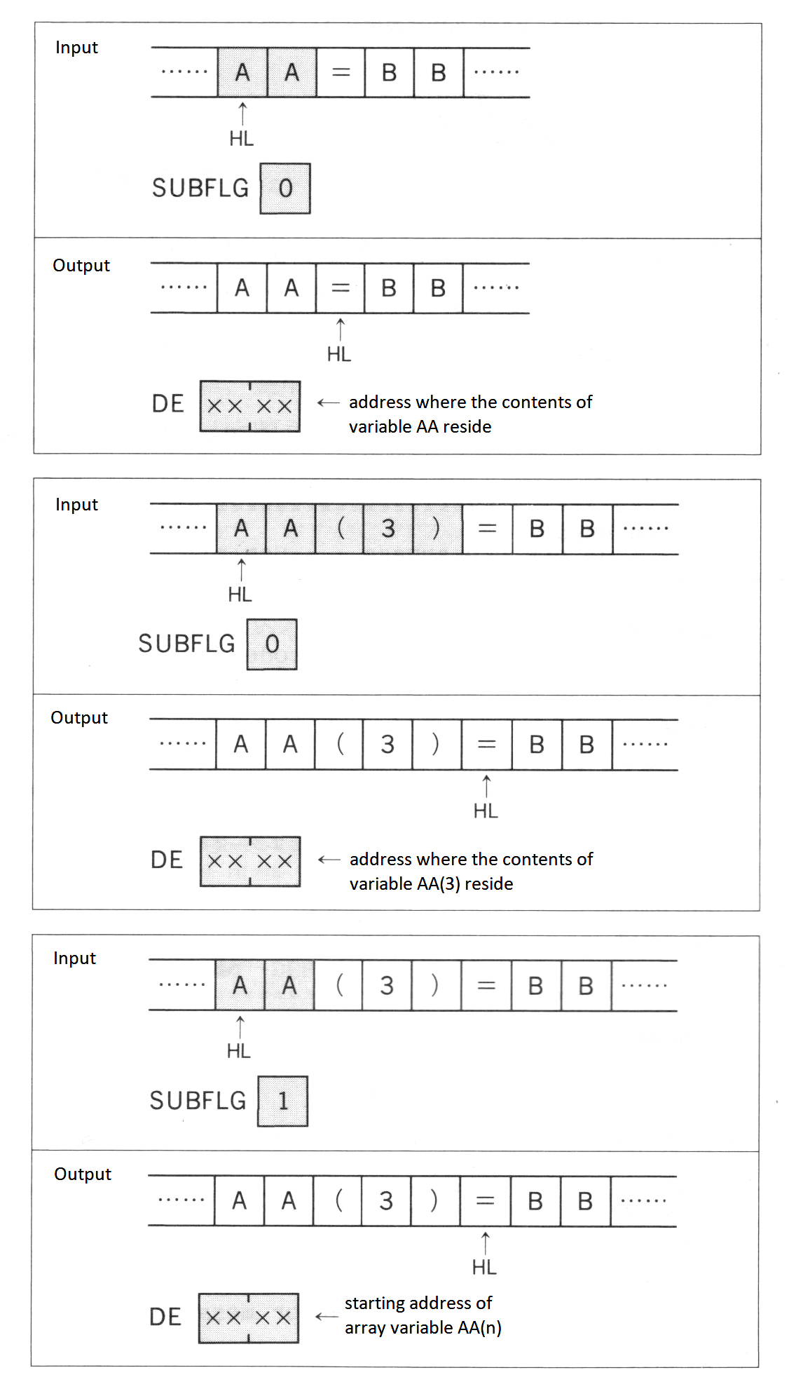
NEWSTT (4601H/MAIN
Execute a text
- Input: HL ⟵ Address of the text to be executed
- Output: ----
Purpose: Execute a text. The state of the text is necessary to be as same as shown in Figure 2.17.
Figure 2.17 Memory setting for NEWSTT
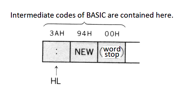
Since these internal routines are for BASIC texts, the same error handling as BASIC is done when an error occurs. In this case, by changing H.ERROR (FFB1H), the user can handle the error (the E register contains the error number) (see List 2.3).
List 2.3 Changing error handling routine
;****************************************************************
;  List 2.3   Your own error
;             To use,   do DEF USR=&HB000 : A=USR(0)
;****************************************************************
;
HERR    EQU     0FFB1H          ;error hook
SYNERR  EQU     2               ;syntax error code
CHPUT   EQU     0A2H            ;character output
NEWSTT  EQU     4601H           ;run
READYR  EQU     409BH

        ORG     0B000H
                                Note:
;----- command initialize ----- When this portion is executed, the error handling routine is changed.

        LD      BC,5            ;SET NEW HOOK
        LD      DE,HERR
        LD      HL,HDAT
        LDIR
        RET

HDAT:   JP      ERROR
        NOP
        NOP
                                Note:
;----- error routine -----      Error handling body

ERROR:  LD      A,E             ;when in error, E holds error code
        CP      SYNERR          ;syntax error ?
        RET     NZ              ;no

        LD      HL,DATA1        ;yes
LOOP:   LD      A,(HL)          ;put new error message
        CP      "$"
        JR      Z,EXIT
        PUSH    HL
        CALL    CHPUT
        POP     HL
        INC     HL
        JR      LOOP

EXIT:   JP      READYR          ;BASIC hot start

DATA1:  DEFM    OOHPS!!         ;new error message
        DB      07H,07H,07H,"$"

        END
4.5 Interrupt usage
The Z80 CPU has INT and NMI interrupt terminals. The MSX, however, uses only INT. The INT terminal gets 60 Hz signals, so timer interrupts are executed 60 times per 1 second. As the interrupt mode of Z80 is set to 1, 38H is called when an interrupt occurs and then the system control jumps to the timer interrupt routine, where various operations such as key input are done.
The timer interrupt routine jumps to hook H.TIMI (FD9FH) in mid course. Using this hook enables the user to add a function to this timer interrupt routine. Thogh there is ordinarily only a RET command, be careful when peripherals such as disks are connected and this hook is already in use. In this case, careless modifications causes peripherals to be disabled, so prearrangement is necessary to make machines to execute that normally. List 2.4 is an example of this handling and the interrupt usage.
List 2.4 Correct usage of timer interrupt hook
;*************************************************************
;   List 2.4   How to use HOOK safety
;              This routine uses TIMER INTERRUPT HOOK
;                                  and turn on/off CAPS LOCK
;              To start, do  DEF USR=&HB000 : A=USR(0)
;              To end,   do  DEF USR=&HB030 : A=USR(0)
;*************************************************************
;
CHGCAP  EQU     0132H           ;CAPS LAMP on/off
CAPST   EQU     0FCABH          ;CAPS LOCK status
TIMI    EQU     0FD9FH          ;timer interrupt hook
JPCODE  EQU     0C3H
TIMER   EQU     020H

        ORG     0B000H

;----- interrupt on ----- Note:  restore the former hook when changing the hook

INTON:  DI
        LD      HL,TIMI         ;OLD HOOK SAVE
        LD      DE,HKSAVE
        LD      BC,5
        LDIR

        LD      A,JPCODE        ;NEW HOOK SET
        LD      (TIMI),A
        LD      HL,INT
        LD      (TIMI+1),HL
        EI
        RET

        ORG     0B030H

;----- interrupt off ----- Note:  restore the reserved hook and exit

INTOFF: DI
        LD      HL,HKSAVE
        LD      DE,TIMI
        LD      BC,5
        LDIR
        EI
        RET

;----- interrupt routine -----

INT:    PUSH    AF
        LD      A,(CAPST)
        OR      A
        JR      Z,CAPON

CAPOFF: LD      A,(COUNT1)
        DEC     A
        LD      (COUNT1),A
        JR      NZ,FIN
        LD      A,TIMER
        LD      (COUNT1),A
        XOR     A
        LD      (CAPST),A
        LD      A,0FFH
        CALL    CHGCAP
        JR      FIN

CAPON:  LD      A,(COUNT2)
        DEC     A
        LD      (COUNT2),A
        JR      NZ,FIN
        LD      A,TIMER
        LD      (COUNT2),A
        LD      A,0FFH
        LD      (CAPST),A
        XOR     A
        CALL    CHGCAP

FIN:    POP     AF
        CALL    HKSAVE          ;old HOOK call

        RET

COUNT1: DEFB    TIMER
COUNT2: DEFB    TIMER

HKSAVE: NOP                     ;old HOOK save area
        NOP
        NOP
        NOP
        RET

        END
5. NOTES ON SOFTWARE DEVELOPMENT
There are some matters, when developing the software for MSX, that should be followed so as to make the software work without any problems on any MSX machines. The following describes these matters and introduces information that will help you develop software.
BIOS
The purpose of BIOS is to separate the hardware and the software and to make the software still valid if the hardware changes. Applications for sale which manage input and output should use BIOS (except for VDP).
BIOS is called through the jump table which begins at 0000H of MAIN-ROM. Though MSX2 has a jump table on SUB-ROM, it is used for calling the extended functions. The branch destination of the jump table or, the contents of BIOS may be modified for the hardware modification or the extension of the function, so applications should not call them directly. Thogh this book has some examples that call addresses other than the BIOS jump table, you should consider them for information only (see BIOS list in APPENDIX). Applications can call Math-Pack and internal routines for the extended statements described above. These will not be changed in the future.
Work area
F380H to FFFFH of MAIN-RAM cannot be used, as it is a work area for BIOS and BASIC interpreter. Free space in the work area cannot be used, because it is reserved for the future use. See 3.1 User's area for the work area of the disk.
Initialisation of RAM and stack pointer
The contents of RAM are unpredictable when the machine is powered and areas other than system work are are not initialised. Applications should initialise the work area. There was once an application which expected the contents of RAM to be 00H and was unusable.
The value of the stack pointer when the INIT routine (see Section 7 of Chapter 5) in the ROM cartridge is called is unpredictable and the value when disk interface has been initialised is smaller than when not. For these reasons some programs which did not initialise the stack pointer had unpredictable results. Programs which are invoked by the INIT routine and continue processing (that is, programs which do not need to use peripherals such as disks or BASIC interpreter) should initialise the stack pointer.
Work area of extended BIOS
When using extended BIOS calls, a stack should be placed above C000H so that CPU can refer to the work area even if the slot is switched over. For the same reason, FCB of RS-232C should be above 8000H.
Work area of device drivers, etc.
Special attention should be paid for the allocation of the work area of programs which reside in memory with another program at the same time, programs such as the device driver or a subroutine called from BASIC.
The INIT routine of the cartridge changes BOTTOM (FC48H), reserves the area between the old BOTTOM and new BOTTOM as its work area, and records the address of the work area to 2-byte area SLTWRK (FD09H) allocated for each slot. For more details, see Section 7 of Chapter 5.
Hook
When using the RS-232C cartridge, change the hook for an interrupt. For example, if another cartridge uses an interrupt hook, the RS-232C cartridge cannot use the same hook. To prevent this, the previous contents of the hook (inter-slot call command for the interrupt handling routine of RS-232C cartridge, in the example above) should be copied to another location, and, when called by the hook, it should be called so that all cartridges intending to use the hook can receive control (see Figure 2.18). For more details, see Section 7 of Chapter 5.
Figure 2.18 Initialisation of the hook
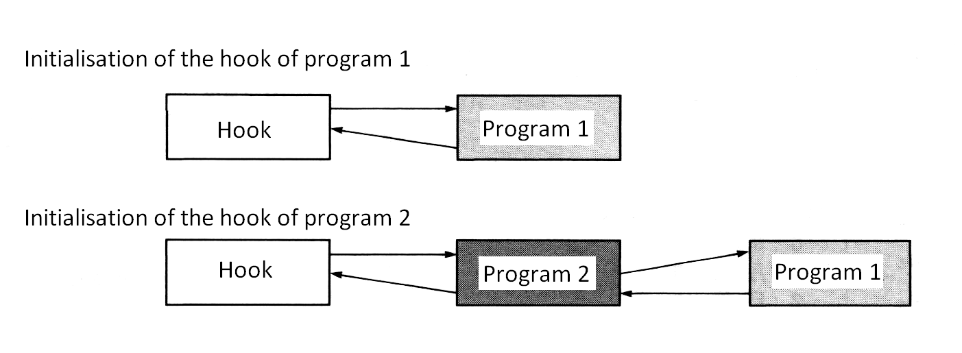
VRAM capacity
The capacity of VRAM can be found by evaluating bits 1 and 2 of MODE (FAFCH) (see Table 2.22).
Table 2.22 Getting the information about the VRAM capacity
----------------------------------
|    [FAFCH]    |                |
|---------------|  VRAM Capacity |
| Bit 2 | Bit 1 |                |
|-------+-------+----------------|
|   0   |   0   |   16K (MSX1)   |
|   0   |   1   |   64K (MSX2)   |
|   1   |   0   |  128K (MSX2)   |
----------------------------------
BASIC version number
The following methods can be used for applications to find out the version number of BASIC.
- Read the contents of 2DH of MAIN-ROM (00H = version 1.0, 01H = version 2.0, and so on).
- In version 2.0 or later versions, EXBRSA (FAF8H) contains the slot address of SUB-ROM. When it has none (00H), the version is version 1.0.
International MSX
There are different kinds of MSX for various countries. The following items are different by country:
- Keyboard arrangement, character set, PRINT USING format
- Timer interrupt frequency
The version of machine can be found by reading the ID byte information in ROM (see Figure 2.19) and the correspondence for MSX of each country will be accomplished (see Table 2.23).
Figure 2.19 Contents of ID byte
-------
| 2BH |   b0  --+
-------         |  character generator
          b1    |
                |  0: Japan     1: United States, etc.
          b2    |  2: USSR
                |
          b3  --+

          b4  --+
                |  date format
          b5    |
                |  0:Y/M/D      1:M/D/Y       2:D/M/Y
          b6  --+

          b7       interrupt period (VSYNC)
                   0:60Hz       1:50Hz


-------
| 2CH |   b0  --+
-------         |  keyboard
          b1    |
                |  0:Japan      1:United States, etc.
          b2    |  2:France     3:United Kingdom
                |  4:Germany    5:USSR          6:Spain
          b3  --+

          b4  --+
                |
          b5    |  information about PRINT USING
                |  or others
          b6    |
                |
          b7  --+
Table 2.23 MSX format for each country
-----------------------------------------------------------------------------
|           |              |          |             PRINT USING             |
|           |              |   Date   |-------------------------------------|
|  Country  |    TV set    |          | Initial  | String | Re-   | Curren- |
|           |              |  format  | screen   | length | place | cy      |
|           |              |          | mode     | specif.| char. | symbol  |
|-----------+--------------+----------+----------+--------+-------+---------|
| Japan     | NTSC  (60Hz) | YY/MM/DD | Screen 1 |   &    |  @    |  (yen)  |
| UK        | PAL   (50Hz) | DD/MM/YY | Screen 0 |   \    |  &    | (pound) |
| Internat. | PAL   (50Hz) | MM/DD/YY | Screen 0 |   \    |  &    |$(dollar)|
| US        | NTSC  (60Hz) | MM/DD/YY | Screen 0 |   \    |  &    |$(dollar)|
| France    | SECAM (50Hz) | DD/MM/YY | Screen 0 |   \    |  &    |$(dollar)|
| Germany   | PAL   (50Hz) | DD/MM/YY | Screen 0 |   \    |  &    |$(dollar)|
| USSR      | NTSC  (60Hz) | MM/DD/YY | Screen 0 |   \    |  &    |$(dollar)|
| Spain     | PAL   (50Hz) | MM/DD/YY | Screen 0 |   \    |  &    |$(dollar)|
-----------------------------------------------------------------------------
Escape sequence
MSX has the escape sequence feature (see Appendix 10), which can be used in the PRINT statement of BASIC, and in console output of BIOS or BDOS call (MSX-DOS). The escape sequence feature is a subset of DEC VT52 terminal and Heathkit H19 terminal.
Returning to BASIC
Warm start
After selecting a slot of MAIN-ROM, jump to 409BH of MAIN-ROM. If the work area of BASIC has not been destroyed, the BASIC prompt will be displayed. The contents of register and stack at the jump are ignored.
Another way is to execute the next command in internal routine NEWSTT (see 4.4 of Chapter 2) (see Figure 2.20)
Figure 2.20 Input setting of NEWSTT for the warm start
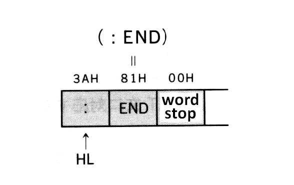
Auto start
In the case of simple game cartridges which do not use the BIOS or BASIC work areas, the program can be invoked by writing a starting address for the program to "INIT" in ROM header. But using this method prevents the initial settings of another cartridge, so disk drives cannot be used.
To prevent this, the hook "H.STKE" is at FEDAH; write the inter-slot call command in the program to be invoked at the execution on "INIT" routine of the cartridge, and return to the system by RET command. Then after initialising all cartridges and after preparing the DISK BASIC environment if there is a disk, the hook is called, so the objective program can be invoked. This method is also effective when there is no disk (see APPENDIX).
Error code list
| Code | Message | Description |
|---|---|---|
| 1 | NEXT without FOR | There is no FOR statement corresponding with the NEXT statement. |
| 2 | Syntax error | There is an error in syntax. |
| 3 | RETURN without GOSUB | The RETURN statement does not correspond to the GOSUB statement. |
| 4 | Out of DATA | There is no data to be READ by the READ statement. |
| 5 | Illegal function call | There is an error in the function or numeric value specification. |
| 6 | Overflow | The numeric value has overflow. |
| 7 | Out of memory | The free area has been exhausted. |
| 8 | Undefined line number | There is no such a line number in the program. |
| 9 | Subscript out of range | The subscript value of the array variable exceeds the declared range. |
| 10 | Redimensioned array | The array is declared twice. |
| 11 | Division by zero | The attempt to divide by zero is made. The negative exponent of zero is done. |
| 12 | Illegal direct | The statement which cannot be executed in the direct mode is carried out directly. |
| 13 | Type mismatch | There is a conflict in the data types. |
| 14 | Out of string space | The string space is exhausted. |
| 15 | String too long | The length of the string is longer than 255 characters. |
| 16 | String formula too complex | The specified string is too complex. |
| 17 | Can't CONTINUE | The CONT command cannot be executed. |
| 18 | Undefined user function | An attempt was made to use the user-defined function which has not been defined by DEF FN statement. |
| 19 | Device I/O error | An error occurred in input/output of device. |
| 20 | Verify error | The program on cassette and the one in memory are not the same. |
| 21 | No RESUME | There is no RESUME statement in the error handling routine. |
| 22 | RESUME without error | The RESUME statement is used other than in the error handling routine. |
| 23 | Undefined. | |
| 24 | Missing operand | Necessary parameters are not specified. |
| 25 | Line buffer overflow | There are too many characters for the input data. |
| 26 to 49 | Undefined. | |
| 50 | FIELD overflow | The field size defined in FIELD statement exceeds 256 bytes. |
| 51 | Internal error | An error occurred inside BASIC. |
| 52 | Bad file number | File number which has not been OPENed is specified. The specified file number exceeds the number specified in MAXFILES statement. |
| 53 | File not found | The specified file is not found. |
| 54 | File already open | The file has already been OPENed. |
| 55 | Input past end | The attempt to read the file is made after reading the end of it. |
| 56 | Bad file name | There is an error in the specification of the file name. |
| 57 | Direct statement | Data other than the program is found while loading the ASCII format program. |
| 58 | Sequential I/O only | Random access to the sequential file is made. |
| 59 | File not OPEN | The specified file has not been OPENed yet. |
| 60 | Bad FAT | Unusual disk format. |
| 61 | Bad file mode | An incorrect input/output operation is made in the OPENed mode. |
| 62 | Bad drive name | There is an error in the drive name specification. |
| 63 | Bad sector number | There is an error in the sector number. |
| 64 | File still open | The file has not been closed. |
| 65 | File already exists | The file name specified in NAME statement already exists on the disk. |
| 66 | Disk full | The free area of the disk has been exhausted. |
| 67 | Too many files | The number of files exceeds 112 (the directory space has been exhausted). |
| 68 | Disk write protected | The disk is protected from writing. |
| 69 | Disk I/O error | Some trouble occurred in the disk input/output. |
| 70 | Disk offline | The diskette is not in. |
| 71 | Rename accross disk | NAME statement is done across different disks. |
| 72 | File write protected | The file has the read-only attribute set. |
| 73 | Directory already exists | The directory name specified in CALL MKDIR statement already exists. |
| 74 | Directory not found | The specified directory is not found. |
| 75 | RAM disk already exists | Attempt to create the DOS 2 RAM disk when it already exists is made. |
| 76 to 255 | Undefined. |
- Note: Errors with codes 72 to 75 are added from version 2 of MSX DISK-BASIC. In version 1 they are undefined.
Use larger numbers first for user error definition.
Changes from the original
-
In description of REM statement,
[<comment>]field has been added. -
In description of SGN function, "Examines the sign and returns..." has been changed to "Examines the sign of
<expression>and returns..." -
Descriptions for MSX DISK-BASIC statements DSKI have been added.
-
Descriptions for new commands on MSX DISK-BASIC version 2 have been added.
-
In Table 2.20 (List of intermediate codes), the code "FC" is shown as assigned to "" as it is actually, and not to "$" as in the original text.
-
In List 2.3 (Changing error handling routine), the third line of "command initialize", which is "LD HL,CMDHDAT" in the original, is corrected to "LD HL,HDAT".
-
In Section 5, "Notes on Software Development", subsection "BASIC version number", the part "and so on" has been added in point 1.
-
In Error code list, description of errors 72 to 75 have been added.