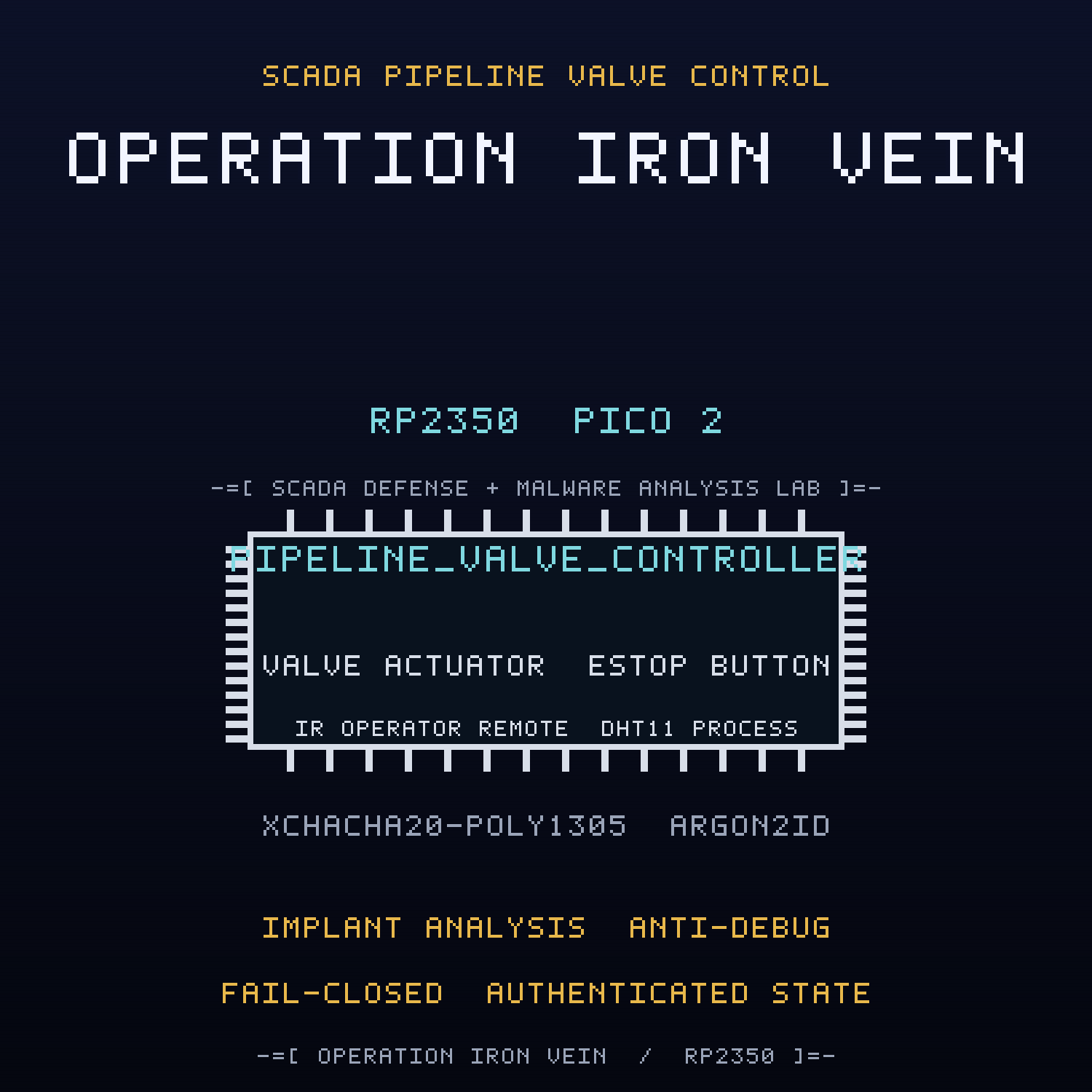
OPERATION IRON VEIN
September 24, 2026 · View on GitHub
FREE Reverse Engineering Self-Study Course HERE
FREE Embedded Hacking Course HERE
OPERATION IRON VEIN
Pipeline Valve Controller
Act III of OPERATION COLD IRON
LEGAL DISCLAIMER: The information, tools, and code provided in this repository and course are strictly for educational, research, and defensive purposes only.
You are explicitly prohibited from using any materials contained herein to access, test, modify, or exploit any device, network, or system that you do not own 100% or for which you do not have explicit, documented, and legally binding authorization to interact with.
By using this repository and course, you acknowledge and agree that:
- Any illegal, unauthorized, or malicious use of this information is solely your responsibility.
- The author(s) and contributor(s) of this repository and course shall not be held liable for any damages, legal repercussions, criminal charges, or unauthorized actions resulting from the use, misuse, or abuse of the contents herein.
- You will comply with all applicable local, state, national, and international laws regarding cybersecurity and computer fraud.
IF YOU DO NOT AGREE WITH THESE TERMS, DO NOT USE THIS REPOSITORY AND COURSE.
Hello, friend.
In Act I you learned that a sensor can lie. In Act II you learned that a door can be told it is safe. This is the third lesson, and it is the quietest one.
The frame you pulled out of the gate carried a route, and the route ended at a pipeline. A NorthPharma pumping station with one valve on one line and a controller that reports itself healthy. NIGHTINGALE's last copy came off this rack. So did the thing that is copying back.
WHITEOUT traced the Ministry's tooling here, and the tooling is still running. Not a crash. Not a bug. A payload that is already inside. It lives in the firmware of a controller that was never vulnerable, it beacons when it feels like it, and it waits for one eight-byte word to slam the valve shut on a line that is full of pressure.
This is the first act with a malware track. Acts I and II were vulnerability only; here you hunt a living implant. You will find the beacon, defuse the logic bomb, and walk a debugger straight past an anti-debug trap that turns the implant polite whenever a probe is watching.
Do not unplug it yet. Read it first. Then remove it.
The valve is working. That is the problem.
THE SYSTEM
NorthPharma does not only move cold medicine. It moves the fluid that makes the medicine: feedstocks, solvents, chilled reagent, the chemistry that has to arrive on time and at temperature. The pipeline is the reach of the cold chain, and the valve controller is the hand at the end of it.
A SCADA valve is a simple machine. A process sensor reports the line, an operator requests an open or a close, an actuator moves the valve, and an annunciator says whether the line is nominal. The failure that matters is not a wrong number on a screen. It is a valve that moves when no one asked, on a line that is not ready. That is the difference between a bad reading and a bad event.
The controller in this repository is that hand. On a breadboard it is a toy: a Pico 2, a servo that acts as the valve, a DHT11 that stands in for the process sensor, an infrared remote that stands in for the operator, a button that is the emergency stop, a 1602 LCD that is the SCADA readout, three lamps, and a radio.
Nothing about it looks broken. That is the horror of Act III. The code compiles, the tests pass, the annunciator is green, and there is an implant inside it that was put there on purpose.
THE STAKES
Act I was a lie about temperature. Act II was a lie about people. Act III is a lie about machinery, and it is the first lie that can hurt someone without a person in the loop.
The controller is weaponized, not buggy. A hidden implant beacons over LoRa on a timer, and a logic bomb arms on a single magic word and then closes the valve on its own schedule. Close a valve on a live line and the pressure has nowhere to go. The process does not care that the firmware passed its tests.
And here is the part that keeps the engineers awake. The valve command path is already authenticated. The cryptography is real and it is correct. The implant does not break the cipher. It does something worse: it lives on the same chip and calls the actuator directly, with no operator, no request, and no authorization. You cannot patch a protocol if the attacker is already inside the protocol.
That is not a valve controller. That is a valve controller with a second owner.
WHITEOUT
WHITEOUT is a resistance that does not exist on paper. It does not hold ground and it does not hold press conferences. It reads firmware. When NIGHTINGALE copied the shipping image and went quiet, the crew kept pulling the thread. The monitor led to the gate. The gate led to the pipeline. The pipeline is where the Ministry stopped hiding behind a vendor and started shipping the tool itself.
NIGHTINGALE is still the thread. Her last verified copy came off this controller, and it was clean. The thing that came after it was not. Somewhere between the build server and the rack, someone signed a firmware image that carries a payload, and that image is running on the line right now.
WHITEOUT's job in Act III is not to break in. It is to prove the machine is already broken, in writing, with a debugger and a disassembler, and then to remove the thing that does not belong.
THE MACHINE
The firmware in this repository is the controller's firmware. On a breadboard it is a toy: a Pico 2, an SG90 servo that is the valve, a DHT11 that is the process sensor, a VS1838B infrared eye that takes an operator remote, a 1602 LCD SCADA readout over I2C, red/yellow/green annunciator lamps, an emergency-stop button, and an RYLR998 LoRa link to a SCADA gateway.
Two things are open, and one thing is not what it seems. The optical surface
takes an operator command from any NEC remote, and it is not authenticated. The
radio carries the sealed command path, and it is authenticated correctly. The
part that is not what it seems is the implant: a module compiled only under a
build flag called SANDBOX_ONLY, invisible in the clean firmware, and present in
the test and CTF builds. It beacons, it arms, it waits, and it hides from the
debugger.
The face of the thing is honest in the way that matters least. The lamps say VALVE FAULT, COMMAND PENDING, and VALVE NOMINAL with total confidence, and the LCD shows the state and the link. None of it lies. A healthy machine can still be a hostile one.
THE JOB
You do not have to be a hero. You have to be honest. The controller is carrying a passenger that no design review admitted to. Find it, prove it, and take it out.
- Bring it up. Build the clean firmware, wire the board, and confirm the controller reads the process sensor, takes an operator command, reaches the gateway, and moves the valve. Nothing looks broken because nothing is broken yet.
- Hunt the malware. Build the
SANDBOX_ONLYimage and find the beacon, the logic bomb trigger, the anti-debug trap, and the persistence marker. This is the first act where the target is not a flaw but a payload. - Defuse it. Disarm the beacon, disarm the logic bomb, and step past the anti-debug with GDB so the implant cannot tell that a probe is attached.
- Fix the machine. Seal the valve command path so only an authorized gateway can move the valve, give the emergency stop absolute priority, and make the valve fail closed on a lost link or a fault.
This document is the manual for the job. Work it on a breadboard. When the green lamp is lit and the valve still moves on its own, remember what it is: not a healthy machine. A hijacked one.
Goodbye, friend.
A NOTE ON THE ROADMAP
This project is Act III of OPERATION COLD IRON. Act I was the sensor (cold-chain-monitor). Act II was the door (access-gate). Act III is the valve. All three are defended devices; the companion CTF repository ships the compromised one. The investigation lives here:
The CTF is the red half, weaponized: six deep tasks, each with static analysis, a dynamic proof under GDB, a hardware demonstration, and an in-place, same-size patch. This repository is the defended device. The CTF repository is the breached one. The full story lives at github.com/mytechnotalent/pipeline-valve-controller.
WHERE THIS FITS: OPERATION COLD IRON
This repository is Act III (IRON VEIN) of the ten-act OPERATION COLD IRON saga. Acts I and II are the vulnerability-only foundation; the malware track begins here. The full spine is in SAGA.md.
- Previous act: Act II, IRON GATE, the access gate, access-gate
- This act: Act III, IRON VEIN, the pipeline valve controller
- Next act: Act IV, IRON LUNG, hvac-automation-node (forthcoming)
- Companion CTF: CTF_pipeline-valve-controller
THE MINISTRY
The Ministry runs the state: the surveillance, the cold chain, the gates, the pipelines. NorthPharma is one of its deniable industrial fronts, and FROSTLINE is the contractor that does the work no Ministry letterhead will admit to. FROSTLINE did not break into this controller; it built the implant, signed the image, and moved on. Against them is WHITEOUT, and the engineer who copied the first image, NIGHTINGALE. This act is one node of the Ministry's industrial edge. TELESCREEN, the surveillance backbone that watches it, comes after the ten.
An adversarial, evidence-based audit of this act, including its honest limitations, is in NATION-STATE-REVIEW.md.
How This Project Fits the Embedded Hacking Course
This repository is the Act III capstone integration for the Embedded Hacking course. It reuses the entire Act I peripheral set so one breadboard serves the whole foundation, and it adds the concepts the later acts build toward: an in-firmware implant, covert beaconing, a logic bomb, anti-debug behavior, persistence preview, and the blue-half controls that contain them.
Each earlier module teaches one peripheral or language concept in isolation; this project wires several of them into a single, tested product, and then teaches you to look at that product as an adversary sees it.
| Embedded Hacking module | Concept you learn | Where it lives here |
|---|---|---|
| Week 1: Introduction, Ethics, Scoping | Authorized lab work | Every lab is self-contained and authorized by design |
| Week 3: RP2350 Architecture and Firmware Analysis | Bare-metal targets, ELF/UF2, SWD | Pico SDK build, build/*.uf2, Debug Probe flash via OpenOCD |
| Weeks 4-6: Variables, Integers/Floats, Static | Data types, GPIO | src/monitor.c state machine, LED on GP25 |
| Week 7: Constants with 1602 LCD I2C | I2C bus, HD44780 commands | src/display.c |
| Week 9: Operators with DHT11 | Bit operations, edge timing | src/sensor.c process sensor |
| Week 11: Structures and Functions | Modular design | include/*.h and src/*.c module boundaries |
| This project adds | UART AT driver, LoRa command link, sealed command path, anti-replay, authenticated state, fail-closed policy, malware analysis, anti-debug evasion, strict testing | src/radio.c, src/control.c, src/valve_auth.c, src/implant.c, scripts/gateway.py, scripts/spoof.py, test/ |
If you have not worked through Weeks 7 and 9 yet, do those first: this project assumes you are comfortable with I2C wiring and one-wire edge timing.
Learning Objectives
By the end of this chapter and its labs you will be able to:
- Explain why a control system must protect integrity, availability, and state together, and why an authenticated protocol does not protect the actuator from code that already runs on the same chip.
- Wire and drive a 1602 LCD through a PCF8574 I2C backpack and render a SCADA status and alarm readout.
- Decode a VS1838B infrared receiver as an operator remote for OPEN, CLOSE, and ESTOP commands, and explain why an unauthenticated optical surface is still an attack surface.
- Drive an SG90 valve actuator with 50 Hz PWM and explain why a 1000uF bulk capacitor is not optional.
- Read a DHT11 process sensor and classify the line against a safe band before the valve is allowed to move.
- Design a sealed valve command path over a sub-GHz LoRa link using a fixed-size envelope, a monotonic anti-replay window, and a keyed state tag.
- Analyze a benign implant: locate a covert beacon, identify the logic bomb arming magic, understand the anti-debug trap, and read the persistence marker.
- Defeat an anti-debug check under GDB by understanding the CoreDebug
DHCSRregister at0xE000EDF0. - Apply blue-half controls: sealed and authorized commands, emergency-stop priority, fail-closed behavior, and containment for the implant.
- Derive a key with Argon2id, seal every frame with XChaCha20-Poly1305, and read and run a native host test suite with hardware mocks and line coverage.
Prerequisites
- The Embedded Hacking
breadboard (
EHP2_bb.png) and parts list. - Acts I and II are helpful but not required. See cold-chain-monitor and access-gate for the sensor and the door. The pin map is identical, so one breadboard serves all three.
- Comfort with C, the Linux/macOS shell, and basic electronics.
- A Pico 2, a Debug Probe (recommended, and required for the malware lab), a 1602 LCD with PCF8574 backpack, a DHT11, the full Embedded Hacking kit (3 LEDs, 3 resistors, a push button, an SG90 servo, a 1000uF capacitor, and a VS1838B infrared receiver plus NEC remote), two RYLR998 modules, and one USB-to-TTL serial adapter.
- Toolchain: Pico SDK 2.2.0+,
arm-none-eabi-gcc, CMake, Ninja, Python 3, GDB (arm-none-eabi-gdb) for Lab 3, and (optionally)typstto rebuild the paper.
Table of Contents
- Background
- System Architecture
- The Wire Protocol
- The Cryptographic Envelope
- Hardware You Need
- Wiring the Node
- Build and Flash
- Lab 1: Bring-Up and Verify
- Lab 2: Inspect the Wire Protocol
- Lab 3: The Malware Track
- Lab 4: The Fix Track
- Troubleshooting
- Testing Philosophy and Coverage
- Generating Packet Artifacts
- Code Standards
- Project Layout
- Glossary
- Further Reading
- License
Background
Why SCADA valve control
A SCADA pipeline is a control loop stretched across geography. A process sensor reports the line, a controller decides, an actuator moves, and a gateway logs what happened. The valve is where the decision becomes physical. Everything interesting in industrial control happens in that transition from a number to a motion.
Three properties have to hold at once, and they are not the same property:
- Integrity. The command that reaches the valve is the command the operator or the gateway authorized. Not a replay, not a forgery, not a stray angle.
- Availability. The valve is there when the process needs it. A jammed radio or a crashed controller can be as dangerous as a hostile one.
- State. The controller knows whether it is open, closed, moving, or faulted, and it does not trust a stale or tampered verdict.
Act III adds a fourth property that no protocol can provide from the outside: exclusivity. Only the controller's own logic should be able to move the valve. An implant that runs on the same chip is inside the trust boundary.
Why integrity plus availability plus state matter
The classic naive controller collapses the three. It accepts any command on the radio, it has no anti-replay window, and it keeps its verdict in plain SRAM. Act II showed what that costs a door. Act III shows the industrial version:
- Integrity without exclusivity. The sealed command path in this build is correct. XChaCha20-Poly1305 authenticates every frame, the sequence window rejects a replay, and the state tag detects a tampered verdict. None of that stops an implant that calls the actuator directly.
- Availability as the attack goal. A logic bomb does not need to steal anything. It needs to close a valve at the wrong moment. Denial is the whole payload.
- State as the last line of defense. A keyed tag over the authorization record means a debugger that rewrites the record is caught before the actuator moves. It is the same lesson Act II taught, carried into the valve.
The fix track in Lab 4 seals the command path, gives the emergency stop absolute priority, and makes the valve fail closed. The malware track in Lab 3 removes the passenger that was never in the design.
Why ChaCha20 over AES on the RP2350
The RP2350 has no hardware AES engine; its accelerated crypto block covers SHA-256, not AES. A software AES implementation on this part is therefore both slower and riskier, because table-driven AES performs data-dependent memory accesses that create a cache-timing side channel. ChaCha20 is built only from addition, rotation, and XOR, with no data-dependent table lookups, so it is fast in portable C and has no comparable cache-timing surface. XChaCha20-Poly1305 is thus both the modern choice and the pragmatic one for this silicon. The full rationale, including the extended-nonce benefit, appears in The Cryptographic Envelope.
The two on-wire problems this project solves
- Payloads that contain commas. The sealed body is carried as lowercase hex,
but the
+RCVframing still separates fields with commas. A naive receiver that splits the line on the first comma corrupts the frame. The correct discipline is the declared-length rule: slice exactlyLcharacters after the second comma and require the next character to be a comma. - Telling a real command from a forged or replayed one. The controller records the sender address exactly as the radio reports it, and it trusts the bytes that arrive. The sealed envelope plus the stateful window are what close that gap.
Inter-Integrated Circuit (I2C)
I2C is a two-wire bus: SDA (data) and SCL (clock), each pulled up to the
supply rail. A controller (the Pico) addresses a target by its 7-bit address and
writes or reads bytes. The 1602 LCD backpack carries a PCF8574 I/O expander
at address 0x27; the firmware bit-bangs the HD44780 nibble protocol over that
expander. Pull-ups are mandatory: the firmware enables the internal ones and the
backpack usually adds its own.
The DHT11 one-wire protocol
The DHT11 is a low-cost digital temperature and humidity sensor. In Act III it is the process sensor: the controller classifies the line against a safe band before it will move the valve. It speaks a custom single-wire protocol:
- The host pulls the line low for at least 18 ms (the start pulse), then releases it and enables its pull-up.
- The sensor answers with an 80 us low, then an 80 us high handshake.
- The sensor sends 40 bits. Each bit begins with a 50 us low, then a high
pulse whose width encodes the value: about 26-28 us for a
0, about 70 us for a1. - Five bytes follow: humidity integer, humidity decimal, temperature integer, temperature decimal, and a checksum equal to the low byte of their sum.
Reading it means timing edges on the order of tens of microseconds, so the
firmware uses an 18 ms host pulse, a 50 us bit-classification threshold, and a
240 us per-edge timeout so a dead or unplugged sensor fails fast instead of
hanging the loop. A reading that fails its checksum is never "safe", and a valid
reading outside -5.0 C to 10.0 C (the tenths band -50 to 100) is out of
band. Either way, the process is not nominal.
Universal Asynchronous Receiver/Transmitter (UART) and AT commands
The RYLR998 is driven over a UART at 115200 baud using CRLF-terminated ASCII
commands. The firmware writes AT+SEND=... and drains inbound +RCV=... lines.
Because the radio is a separate processor, its configuration (address, network
identifier, band) persists until changed; the controller and the gateway each
provision their own radio at start-up so they agree before any command traffic
flows.
Cyclic Redundancy Check (CRC)
src/crc.c implements CRC-16/CCITT-FALSE (poly = 0x1021, init = 0xFFFF,
check value 0x29B1 for "123456789"). It is provided as a reusable integrity
diagnostic and exercised by the test suite. It is not part of the LoRa frame
in this project; the lesson is the absence of authentication, not the absence
of a checksum.
System Architecture
There are four roles:
| Role | Runs on | Job |
|---|---|---|
| Valve controller | Pico 2 firmware | Decodes the infrared operator remote, verifies sealed gateway commands, annunciates COMMAND PENDING, checks the process sensor, drives the valve, enforces the emergency stop, and renders the SCADA readout |
| SCADA gateway | laptop + USB-TTL radio | Authenticates every request, logs it to valve_log.csv, decides authorization, and answers with a sealed valve command carrying a sequence and a state tag (scripts/gateway.py) |
| Edge simulator | laptop + USB-TTL radio | Pretends to be a controller and sends sealed requests (scripts/sim_edge.py) |
| Attacker | laptop + USB-TTL radio | Impersonates the gateway, forges a command, or replays a captured command (scripts/spoof.py) |
Data flow
+----------------------+                              +----------------------+
|  Pico 2 valve node   |        LoRa (sub-GHz)        |   SCADA gateway      |
|  IR remote  -> GP5   |  AT+SEND=0001,<len>,<hex>    |  USB-TTL radio       |
|  DHT11      -> GP4   |----------------------------->|  scripts/gateway.py  |
|  Servo      -> GP14  |<-----------------------------|  valve_log.csv       |
|  LCD     -> GP2/GP3  |  AT+SEND=<node>,<len>,<hex>  |  sealed command      |
+----------------------+                              +----------------------+

+----------------------+                              +----------------------+
|   Attacker laptop    |  forged or replayed command  |   (same valve node)  |
|   scripts/spoof.py   |----------------------------->|   rejects at the tag |
|  claims the gateway  |                              |   tag or seq window  |
+----------------------+                              +----------------------+
Firmware module map
| File | Responsibility |
|---|---|
src/main.c | Entry point: stdio_init_all, monitor_init, tick loop |
src/monitor.c | State machine: I2C bus scan, operator remote, gateway command, valve motion, emergency stop, process sensor, SCADA render |
src/implant.c | SANDBOX_ONLY FROSTLINE implant: covert beacon, logic bomb, CoreDebug anti-debug, reserved-sector persistence marker |
src/valve.c | Valve state machine: bounded travel, open/closed/fault/moving, fail closed |
src/control.c | Sealed valve command path: open, authorize, guarded open/close command set |
src/valve_auth.c | Authorization record, monotonic anti-replay window, authenticated state tag |
src/sensor.c | DHT11 one-wire sampling and process-band classifier |
src/display.c | HD44780 driver over the PCF8574 backpack and SCADA status rendering |
src/radio.c | RYLR998 provisioning, AT+SEND builder, +RCV parser, line pump |
src/status_led.c | Red/yellow/green VALVE FAULT / COMMAND PENDING / VALVE NOMINAL annunciator |
src/button.c | Debounced emergency-stop button around the internal pull-up |
src/servo.c | 50 Hz PWM valve actuator |
src/ir_remote.c | VS1838B edge timing and NEC operator remote decode |
src/chacha20.c | ChaCha20 stream cipher and HChaCha20 subkey derivation |
src/poly1305.c | Poly1305 one-time message authenticator |
src/crypto_aead.c | XChaCha20-Poly1305 seal/open envelope |
src/blake2b.c | BLAKE2b and the Argon2 variable-length hash H' |
src/argon2.c | Argon2id core (BLAMKA, hybrid addressing) |
src/crypto_kdf.c | Argon2id passphrase key derivation |
src/envelope.c | Hex nonce/ciphertext/tag envelope codec |
src/crc.c | CRC-16/CCITT-FALSE diagnostic |
include/pipeline_valve.h | Pin map, bus, provisioning, implant addresses |
include/implant.h | Implant beacon, arming magic, anti-debug interface |
include/control.h, include/valve_auth.h | Sealed command and authorization interfaces |
The Wire Protocol
Request frame
The operator remote, or the edge simulator, seals a one-byte valve command into an authenticated envelope and sends it to the SCADA gateway:
AT+SEND=0001,<len>,<hex envelope>
The plaintext of a request is exactly one command byte: VALVE_COMMAND_OPEN
(0x01) or VALVE_COMMAND_CLOSE (0x00). Anything else is out of the guarded
command set and is refused.
Command frame
The gateway answers an authenticated request with a sealed valve command. The command plaintext is a 21-byte body:
seq[4] (little-endian) || cmd[1] || state_tag[16]
seqis the monotonic gateway sequence number.cmdis0x00for close or0x01for open.state_tagis an XChaCha20-Poly1305 tag over the authorization record the command would produce, so the controller can verify that the verdict it is about to store is the one the gateway authorized.
The gateway sends it back to the claimed sender address:
AT+SEND=<node>,<len>,<hex envelope>
The firmware enforces the guard in control_parse: pt[4] > VALVE_COMMAND_OPEN
is rejected, so any command byte above one never reaches the actuator. This is
the sealed replacement for the old unauthenticated angle injection.
Sealed envelope layout
Every payload on the wire is the lowercase hexadecimal encoding of:
nonce[24] || ciphertext[L] || tag[16]
For a one-byte request body this is 24 + 1 + 16 = 41 bytes, or 82 hex
characters. For a 21-byte command body this is 24 + 21 + 16 = 61 bytes, or 122
hex characters. The declared length L in the AT+SEND and +RCV framing is the
length of the hex string, not of the underlying plaintext.
The maximum accepted plaintext is 48 bytes (ENVELOPE_MAX_PLAINTEXT), and the
maximum hex envelope buffer is (24 + 48 + 16) * 2 + 1 = 177 bytes
(ENVELOPE_MAX_HEX_LEN), which fits the 256-byte radio command and receive
buffers with framing headroom.
Declared-length slicing invariant
Given the substring T after the second comma:
C = T[0 : L] and T[L] == ","
The receiver checks T[L] == ",", so a mismatch between the declared length and
the actual payload is a parse error rather than silent corruption. This is what
makes hex-bearing payloads safe to carry and is the same invariant Act I uses.
SCADA status readout
ST:OPEN
PROC:OK LNK:UP
Line 1 is the current valve state: CLOSED, OPEN, MOVING, or FAULT. Line 2
is the process-sensor verdict (OK or BAD) and the gateway link (UP or
--). Exactly one status LED is lit at a time to match: red for FAULT, yellow
while MOVING, green while the valve is nominal.
Radio provisioning
For the link to work, both radios must share the same network identifier and each must have the address the other targets:
- Firmware sets its own radio:
AT+ADDRESS=7,AT+NETWORKID=18. gateway.pysets the gateway radio:AT+ADDRESS=1,AT+NETWORKID=18.
Both radios must also be the same band variant (for example 915 MHz or 868 MHz); band and RF parameters are left at factory defaults, so use matching modules.
Timing
| Quantity | Value |
|---|---|
Gateway link timeout (VALVE_ESTOP_WAIT_MS) | 5000 ms |
Valve travel time (VALVE_TRAVEL_MS) | 1000 ms |
| Emergency-stop debounce | 30000 us |
| DHT11 host start pulse | 18000 us |
| DHT11 bit threshold | 50 us |
| DHT11 per-edge timeout | 240 us |
| LCD I2C clock | 100000 Hz |
| Radio UART baud | 115200 |
| Process safe band | -50 to 100 tenths (-5.0 C to 10.0 C) |
| Servo closed pulse | 500 us |
| Servo open pulse | 1500 us |
| Servo PWM period | 20000 us (50 Hz) |
| Implant beacon interval | 8 ticks |
| Implant trigger delay | 3 ticks |
The Cryptographic Envelope
The radio is the first open path, and it is one a key can close. The fix is
authenticated encryption: every request and every command is sealed so a forged
frame dies at the authentication tag instead of moving the valve. The full
implementation lives in src/chacha20.c, src/poly1305.c, and
src/crypto_aead.c, and every primitive is checked against its published test
vectors in the native suite.
Why XChaCha20-Poly1305
- 256-bit key, 192-bit nonce. The extended nonce means nonces can be drawn at random forever, so the controller never needs a shared counter that a reboot could reuse.
- AEAD in one pass. Confidentiality and integrity come from one operation;
the associated data (the valve node id, byte
0x07) is authenticated even though it is not encrypted. - Constant-time software. ChaCha20 has no data-dependent table lookups, so it has no cache-timing surface. The RP2350 has no hardware AES engine (it accelerates SHA-256 only), which makes software AES both slower and riskier on this silicon.
- 128-bit Poly1305 tag. Guessing a valid tag succeeds with probability .
Why Argon2id
A passphrase is not a key. Argon2id (RFC 9106) is the memory-hard password hash:
it mixes the passphrase with a salt across memory and time so an attacker cannot
cheaply recover the field passphrase from a captured image. The classroom profile
is t=3, p=1, m=64 blocks (CRYPTO_KDF_TIME_COST,
CRYPTO_KDF_PARALLELISM, CRYPTO_KDF_MEMORY_BLOCKS) to fit the RP2350 SRAM
budget. Raise it on the SCADA gateway. The lab salt is the 16 ASCII bytes
coldiron-salt-01.
Key model: one field key
Act III uses a single field key derived with Argon2id from a committed lab passphrase and salt. It seals every frame on the wire and it computes the state tag over the authorization record. In the classroom build the firmware and the gateway derive the same key, so they interoperate with no provisioning step. That is a lab convenience, not a deployment.
The design keeps the key roles separable so students can reason about the real lifecycle: derive, provision per device, use, rotate on a schedule, and retire. A production build provisions key material from one-time-programmable (OTP) memory, keeps the state-tag key off the field device where possible, and rotates without reflashing every controller.
Envelope layout
The sealed frame is carried as hex inside the AT+SEND payload:
nonce[24] || ciphertext[L] || tag[16]
The receiver recomputes the Poly1305 tag over the associated data and ciphertext,
compares it in constant time, and only then decrypts. This envelope is wired end
to end: src/control.c opens the command with src/envelope.c, and the gateway
authenticates before it parses or acts. Authenticated frames carry the valve node
id as associated data, so a frame sealed for one node cannot be relabeled for
another.
Anti-replay and authenticated state
Strong AEAD is necessary and not sufficient. Two stateful controls sit on top:
- Anti-replay sequence window.
src/valve_auth.ckeepslast_seq, the highest sequence number ever accepted.valve_auth_applyaccepts a command only when its sequence is strictly greater thanlast_seq. A captured command, even a perfectly valid one, is rejected on second use. - Authenticated state tag. The authorization record is nine bytes:
granted[1],seq[4],last_seq[4]. The tag is an XChaCha20-Poly1305 tag over that record, computed under the field key with a deterministic nonce built from the sequence number and the domain byte0xA7.valve_auth_state_okrecomputes the tag and compares it in constant time before the valve is allowed to move. A debugger that setsgranted = truewithout recomputing the tag fails here first.
The sequence window and the state tag are independent. The window stops a valid command from working twice; the tag stops an unauthorized verdict from existing at all.
The FROSTLINE Implant
This is the first act with a malware track, and the implant is the reason. It is
real in technique and inert in effect: it runs on your breadboard, it moves your
servo, and it writes to a reserved flash sector that holds nothing else. It is
compiled only when SANDBOX_ONLY is defined, so the clean firmware image contains
no implant at all. The test suite and the companion CTF build with SANDBOX_ONLY
and with the host mock, so every implant path is exercised natively.
What the implant does, in the order the code does it:
- Beacon. Every 8 ticks (
IMPLANT_BEACON_INTERVAL_TICKS) the implant emits a covert frame to the local classroom hub. The frame is the 4-byte magic preambleDE AD BE EF(IMPLANT_BEACON_MAGIC) followed by a 4-byte synthetic status blob: the low and high bytes of the tick counter, the marker byte0xC7, and a byte that reports whether a probe is attached. The beacon carries no real data and targets no external address. - Logic bomb. The implant arms when it sees the exact 8-byte magic command
FROSTLNE(IMPLANT_ARM_MAGIC, the bytes'F' 'R' 'O' 'S' 'T' 'L' 'N' 'E') on an inbound frame. It then detonates 3 ticks later (IMPLANT_TRIGGER_DELAY_TICKS) by calling the valve close path directly, independent of the operator, the gateway, and the authorization record. - Anti-debug. Every tick the implant reads the CoreDebug
DHCSRregister at0xE000EDF0(VALVE_IMPLANT_DHCSR_ADDR). Bit 0 isC_DEBUGENand bit 1 isC_HALT. If either bit is set, the implant returns early and suppresses both the beacon and the bomb. It behaves like a well-mannered firmware module while a probe is attached, and it goes back to work the moment the probe is gone. - Persistence preview. The first time it detonates, the implant erases and
programs the reserved flash sector at
0x103FF000(VALVE_IMPLANT_RESERVE_ADDR), the final 4 KiB sector of external flash, storing the marker byte0xC7(IMPLANT_MARKER_BYTE). It writes exactly once (g_implant_persisted). This is a preview of the Act IV lesson: a payload that survives the thing you did to remove it.
The implant is bounded by construction and by test. It touches only its own
beacon radio frame, its arming latch, the servo close path, and the one reserved
sector. There is no network, no filesystem, no host impact, and no real data.
test_implant_init, test_implant_debug_attached, test_implant_handle_command,
test_implant_beacon, test_implant_anti_debug, test_implant_logic_bomb, and
test_implant_persist_once assert exactly that behavior.
The honest limit is the point of the lab. A sanitized educational implant is still a benign educational implant: it demonstrates the technique, not the tradecraft. The real lesson is detection, and the defense is not a patch to the implant but the removal of the code path and the build flag that allowed it in.
Hardware You Need
Full parts list with links: PARTS.md.
| Qty | Part | Notes |
|---|---|---|
| 1 | Raspberry Pi Pico 2 (RP2350) with headers | The valve controller |
| 1 | Raspberry Pi Debug Probe | SWD flashing, UART0 console, and the Lab 3 anti-debug/GDB work (recommended, effectively required) |
| 1 | Full-size breadboard | |
| 1 | Assorted jumper wires | |
| 1 | 1602 LCD with PCF8574 I2C backpack | SCADA status readout, address 0x27 |
| 1 | DHT11 temperature/humidity sensor | Process sensor (line pressure/temperature analog) |
| 1 | 10K resistor | Only if your DHT11 has no onboard pull-up |
| 3 | 5mm LEDs (red, yellow, green) | VALVE FAULT, COMMAND PENDING, VALVE NOMINAL annunciator |
| 3 | 100, 220, or 330 Ohm resistors | One per LED |
| 1 | Push button (tactile switch) | Emergency stop (ESTOP), active low |
| 1 | SG90 servo motor | The valve actuator |
| 1 | 1000uF 25V capacitor | Bulk decoupling on the servo 5V rail |
| 1 | VS1838B infrared receiver | Operator remote input |
| 1 | NEC-compatible infrared remote | Operator OPEN, CLOSE, and ESTOP commands |
| 3 | RYLR998 LoRa modules with antennas | 2 for the command loop, 3 for the live attack lab |
| 2 | USB-to-TTL serial adapters (FTDI FT232, CP2102, or CH340), 3.3V logic | 1 for the gateway, 1 for the attacker in the live lab |
| 4 | USB cables | Pico 2, Debug Probe, and serial adapter(s) |
How many radios do you actually need?
| Goal | Radios | What is connected |
|---|---|---|
| Legitimate sealed command loop (Labs 1-2) | 2 | 1x RYLR998 on the Pico (UART1) + 1x RYLR998 on a USB-to-TTL adapter (the gateway) |
| Live attack lab (Labs 3-4, watch a forged command land and fail) | 3 | the 2 above + 1x RYLR998 on a second USB-to-TTL adapter (the attacker) |
| Attack concept with no extra hardware | 2 or 0 | read-and-run the offline parser demo, or the unit tests |
A radio never receives its own transmission, and the gateway radio is busy
listening as gateway.py, so the live attack needs a separate attacker radio.
The 2-radio kit runs the whole legitimate system; only the live attack
observation needs the third.
Serial adapter warning: the RYLR998 is not 5V tolerant. Use a 3.3V-logic USB-to-TTL adapter (or set its jumper to 3.3V).
How each part works
Every part in the bill of materials does one physical job and one job in this act:
| Part | How it works | Role in this act |
|---|---|---|
| 1x Full-size breadboard (long) | The two columns of spring-clip tie points sit on a 0.1 inch grid, so every hole in a row is bridged by a metal clip, while the two outer power rails run the full length and distribute power and ground to the whole build. | It is the substrate that holds the Pico 2, LCD, sensor, servo, and radio headers and distributes 3.3V and 5V across the controller. |
| 1x Assorted jumper wires (male-to-male, male-to-female, female-to-female) | Male pins push into breadboard tie points or female headers, female sockets slide over the Pico 2, LCD, and servo header pins, and male-to-female leads bridge a breadboard row to a module header. | They carry power and the I2C, one-wire, UART, PWM, IR, and GPIO signals between the boards. |
| 1x Raspberry Pi Pico 2 with header | The RP2350 pairs two Arm Cortex-M33 cores with 3.3V logic and a GPIO block that exposes ADC, I2C, UART, and PWM, plus the onboard GP25 LED. | It is the valve controller that reads the process sensor, applies sealed commands, drives the valve servo and annunciator, and runs the fail-closed state machine. |
| 1x Raspberry Pi Pico Debug Probe | It drives the two-wire SWD port (SWCLK and SWDIO) to flash and single-step the target, and it also presents a USB UART bridge for the serial console. | It flashes and debugs the controller and is the instrument for the Lab 3 malware work and the fix. |
| 2x USB A-male to USB micro-B cables | USB carries 5V power and a data channel on the same cable, so one cable powers the Pico 2 and presents its USB CDC console while the other powers the Debug Probe and carries its SWD and UART traffic. | They power the two boards and carry the console and debug links. |
| 3x 5mm LEDs (1 red, 1 green, 1 yellow) | An LED is a diode with a forward voltage drop of roughly 2V, so current flows only from the anode to the cathode, and a GPIO pin set high sources that current and lights the lamp. | They are the red VALVE FAULT, yellow COMMAND PENDING, and green VALVE NOMINAL annunciator, and exactly one is lit per state. |
| 3x 100, 220, or 330 Ohm resistors | A resistor in series with each LED sets the current by Ohm's law, I equals (supply minus forward voltage) divided by resistance, which protects the LED and keeps the GPIO within its current limit. | One resistor per lamp limits the LED current on each of the three annunciator pins. |
| 1x Push button (tactile switch) | The switch shorts its input pin to ground when pressed, and the RP2350 internal pull-up holds that pin high at rest so the press reads as active low. | It is the emergency stop that latches a fault and forces the valve closed with priority over any remote command. |
| 1x 1602 LCD with PCF8574 I2C backpack | The HD44780 controller takes a 4-bit nibble protocol with register-select and enable strobes, and the PCF8574 I2C expander latches those eight control lines so the whole display is driven over two I2C wires at address 0x27. | It renders the SCADA status and alarm readout. |
| 1x DHT11 temperature and humidity sensor | The host pulls the single data line low for a start pulse, then the sensor answers with 40 bits of humidity, temperature, and checksum timed by pulse widths, and the checksum must match. | It is the process sensor whose reading marks the line not nominal when it fails or leaves the -5.0 C to 10.0 C band. |
| 1x SG90 servo motor | The servo expects a 50 Hz PWM signal whose high pulse of 1 to 2 ms selects the shaft angle, and a Pico PWM slice generates that pulse train. | It is the valve actuator, seated closed at 0 degrees and open at 90 degrees. |
| 1x 1000uF 25V capacitor | Wired across the servo 5V rail and ground, the capacitor is a bulk reservoir that supplies the motor inrush current and smooths the rail while the servo starts. | It keeps the valve move from browning out the RP2350 and resetting the controller. |
| 1x Infrared (IR) receiver (VS1838B) | The receiver pairs a photodiode with a 38 kHz bandpass demodulator that ignores ambient light and outputs an active-low logic pulse for each IR burst. | It is the operator remote input that captures OPEN, CLOSE, and ESTOP on GP5. |
| 1x Infrared (IR) remote controller (NEC-compatible) | The remote emits its bursts modulated at 38 kHz in the NEC frame, a 9 ms leader followed by 32 bits where the address and command are each sent with their bitwise complements for validation. | It is the operator handheld that sends OPEN 0x47, CLOSE 0x45, and ESTOP 0x46. |
| 1x RYLR998 LoRa radio module | The module is configured and driven over UART with AT commands and carries sub-GHz LoRa packets, and its logic pins are 3.3V only so the radio must never see 5V. | It is the UART1 command and status link that carries the sealed frames between the controller and the SCADA gateway, and it is not 5V tolerant. |
Wiring the Node
Pin map
This is the authoritative map; it is identical to Act I and Act II and is defined
in include/pipeline_valve.h and enforced by the test suite.
| Peripheral | Signal | Pico 2 GPIO |
|---|---|---|
| DHT11 process sensor | DATA (one-wire) | GP4 |
| 1602 LCD (PCF8574) | SDA (I2C1) | GP2 |
| 1602 LCD (PCF8574) | SCL (I2C1) | GP3 |
| RYLR998 | RX <- Pico TX (UART1) | GP8 |
| RYLR998 | TX -> Pico RX (UART1) | GP9 |
| Infrared operator remote | OUT (VS1838B) | GP5 |
| Valve servo | PWM signal | GP14 |
| Red VALVE FAULT LED | anode | GP16 |
| Yellow COMMAND PENDING LED | anode | GP17 |
| Green VALVE NOMINAL LED | anode | GP18 |
| Emergency stop button | to ground | GP15 |
| Onboard LED | heartbeat | GP25 |
| Debug Probe / UART0 console | TX | GP0 |
| Debug Probe / UART0 console | RX | GP1 |
Note: GPIO 2/3 are the classic I2C1 pins used throughout the Embedded Hacking breadboard; this project's map matches that board because it is the same board.
1602 LCD with I2C backpack
| LCD backpack | Pico 2 |
|---|---|
| VCC | 3.3V |
| GND | GND |
| SDA | GP2 |
| SCL | GP3 |
DHT11 process sensor
| DHT11 | Pico 2 |
|---|---|
| VCC | 3.3V |
| DATA | GP4 |
| GND | GND |
If your DHT11 has no onboard pull-up, add a 10K resistor between DATA and
3.3V. The firmware also enables the internal pull-up, but the external resistor
makes reads far more reliable over jumper wires. The process is not nominal when
the sensor fails or reads outside -5.0 C to 10.0 C.
Status LEDs
| LED | Pico 2 | Series resistor |
|---|---|---|
| Red (VALVE FAULT) | GP16 (anode) | 220-330 Ohm to GND |
| Yellow (COMMAND PENDING) | GP17 (anode) | 220-330 Ohm to GND |
| Green (VALVE NOMINAL) | GP18 (anode) | 220-330 Ohm to GND |
Exactly one lamp is lit at a time. Red is a valve fault or a failed-closed latch, yellow is a pending command or a moving valve, and green is a nominal line.
LED behavior
| State | Lamp | Indication | Meaning |
|---|---|---|---|
VALVE_OFF | none | All dark | Defined but never selected; the live state machine always drives fault, pending, or nominal. |
VALVE_FAULT | Red | Solid | Valve fault, failed-closed latch, or the latched emergency stop. |
VALVE_PENDING | Yellow | Solid | The valve is travelling after an accepted command. |
VALVE_NOMINAL | Green | Solid | The valve is seated closed or fully open on a nominal line. |
The three annunciator lamps are always solid; status_led.c never blinks them.
Exactly one lamp is lit at a time, and VALVE_OFF leaves all three dark. A
latched emergency stop forces VALVE_FAULT regardless of the valve state. The
onboard GP25 LED is initialized as an output and driven as a heartbeat:
monitor.c toggles it every four monitor ticks in monitor_heartbeat, so a
running controller is visible even while idle.
Emergency stop button
| Button | Pico 2 |
|---|---|
| Leg 1 | GP15 |
| Leg 2 | GND |
The firmware enables the internal pull-up, so do not connect 3.3V to the button. This is the operator's hard stop: a press consumes one debounced edge, latches a fault, and forces the valve closed with priority over any remote command. Lab 4 explains how the priority is enforced and why it must be absolute.
SG90 valve servo
| Servo | Pico 2 |
|---|---|
| Signal (orange) | GP14 |
| VCC (red) | 5V (VBUS) |
| GND (brown) | GND |
Solder the 1000uF capacitor across the servo 5V and GND rails to absorb the inrush current; without it the RP2350 can brown out when the valve moves. Seated (closed) is 0 degrees and open is 90 degrees.
Infrared receiver
| VS1838B | Pico 2 |
|---|---|
| OUT | GP5 |
| VCC | 3.3V |
| GND | GND |
Point any NEC-compatible remote at the receiver. In Act III this is the operator
remote, not a maintenance extra: the firmware decodes MONITOR_IR_OPEN
(0x47), MONITOR_IR_CLOSE (0x45), and MONITOR_IR_ESTOP (0x46). There is
no challenge and no secret on the optical surface, so the firmware applies the
operator command directly; the fix track adds the missing authorization.
Using the remote
Point the NEC remote at the VS1838B receiver on GP5 and press a mapped button;
the receiver idles high and pulls low on a mark. Every valid frame prints
IR <NAME> (0xNN) on the console and is applied to the valve, unless the
emergency stop is latched.
| NEC command | Name | Action |
|---|---|---|
0x47 | MONITOR_IR_OPEN | Drives the valve to the open position (valve_apply_command(true, true)). |
0x45 | MONITOR_IR_CLOSE | Drives the valve to the closed position (valve_apply_command(false, true)). |
0x46 | MONITOR_IR_ESTOP | Latches the emergency stop and forces the valve closed with priority over later commands. |
Once the emergency stop is latched, every further optical command is ignored until the controller is reset.
RYLR998 LoRa radio
The RYLR998 must be powered. Forgetting VDD is the single most common reason the link appears dead: the firmware prints while the radio sits silent.
| RYLR998 | Pico 2 |
|---|---|
| VDD | 3.3V |
| GND | GND |
| RXD | GP8 (Pico UART1 TX) |
| TXD | GP9 (Pico UART1 RX) |
Attach the antenna before transmitting. TX and RX are crossed: the radio's RXD is the Pico's TX and vice versa.
Debug Probe (recommended)
| Debug Probe | Pico 2 |
|---|---|
| SWCLK | SWCLK (3-pin debug header) |
| SWDIO | SWDIO |
| GND | GND |
| UART TX | GP1 (Pico RX) |
| UART RX | GP0 (Pico TX) |
| GND | GND |
The firmware enables stdio on both UART0 (115200) and USB, so you can
watch boot output on the probe's console or on the Pico's own USB serial port.
The Debug Probe is also the instrument for the Lab 3 malware work: it is how you
watch the beacon, trigger the bomb, and step past the anti-debug trap.
Peripherals used
Every part in the Act III bill of materials is exercised by the firmware:
| Peripheral | Role | Where it is used |
|---|---|---|
| Red, yellow, green LEDs | Tri-color SCADA valve annunciator | status_led.c drives exactly one lamp per state |
| Emergency stop button (GP15) | Operator hard stop | button.c consumes one debounced press in monitor_handle_estop |
| 1602 I2C LCD | SCADA status and alarm readout | display.c renders the formatted lines over I2C1 |
| DHT11 (GP4) | Process temperature and humidity | sensor.c reads the one-wire frame every telemetry interval |
| SG90 servo (GP14) | Valve actuator | servo.c drives the valve open and closed |
| 1000uF capacitor | Bulk decoupling on the servo 5V rail | Required to keep the RP2350 from browning out on servo moves |
| VS1838B IR receiver (GP5) | Operator remote input | ir_remote.c captures and decodes the frame |
| NEC IR remote | Operator OPEN, CLOSE, and ESTOP | Sends 0x47, 0x45, and 0x46 |
| RYLR998 (UART1) | LoRa command and status link | radio.c sends sealed frames and pumps inbound commands |
| Onboard GP25 LED | Onboard heartbeat | monitor.c toggles it every four monitor ticks in monitor_heartbeat |
| Debug Probe | SWD flashing, UART0 console, and malware analysis | stdio is enabled on both UART0 115200 and USB |
Every Act III peripheral in the bill of materials is exercised by the firmware.
How the functionality works
Every input feeds the state machine in monitor_step, every output is driven
once per tick, and the interactive console mirrors both over UART0 and USB. The DHT11 is sampled every two seconds, so one live status line appears
about every two seconds. This
is what each surface does at run time.
Inputs
| Input | What it does when you use it |
|---|---|
| Infrared remote (GP5) | A decoded NEC frame prints IR <NAME> (0xNN) and is applied as an operator command, unless the emergency stop is latched. |
| Emergency stop button (GP15) | A debounced press prints BUTTON emergency stop -> valve fault, latches the fault, and forces the valve closed with priority over any remote command. |
| DHT11 (GP4) | The process sensor is sampled every tick; a good read prints a live status line, and a failed read prints SENSOR read failed -> WARNING. |
| RYLR998 (UART1) | Each inbound +RCV frame prints RX from 0xNNNN, N bytes and is offered to the sealed command path. |
Outputs
| Output | What it shows |
|---|---|
| Red, yellow, green LEDs | Exactly one solid lamp per state, red VALVE FAULT, yellow COMMAND PENDING or MOVING, green NOMINAL, and all three dark only in the unused OFF state; status_led.c never blinks them. |
| 1602 I2C LCD | ST:<state> on the first line and PROC:<verdict> LNK:<state> on the second, refreshed every tick. |
| SG90 servo | The valve, seated closed at 0 degrees and open at 90 degrees, with the emergency stop forcing it closed. |
| Onboard GP25 LED | The heartbeat, toggled every four monitor ticks in monitor_heartbeat. |
Watching the console
Open the UART0 console (Debug Probe) or the Pico's own USB serial port at
115200. The boot banner and control hint name the remote buttons and the push
button:
=== OPERATION IRON VEIN // ACT III SCADA PIPELINE ===
REMOTE: CH+ 0x47 open | CH- 0x45 close | CH 0x46 estop
BUTTON: GP15 emergency stop
While the controller runs, a process read prints one live status line and each event prints a named line:
PROCESS t=23 h=610 ok=1 ST=CLOSED n=4
IR OPEN (0x47)
RX from 0x0001, 122 bytes
BUTTON emergency stop -> valve fault
SENSOR read failed -> WARNING
The status line carries the sensor value (t and h), the process verdict
(ok), the annunciator state (ST), and a running status count (n). The event
lines cover a decoded remote command, a button press, an inbound radio frame, and
a failed sensor read.
Build and Flash
1. Install toolchain prerequisites
- Pico SDK 2.2.0+
- ARM GNU toolchain (
arm-none-eabi) - CMake and Ninja
- Python 3.x
- GDB (
arm-none-eabi-gdb) for the Lab 3 malware analysis
Linux:
export PICO_SDK_PATH="$HOME/.pico-sdk/sdk/2.2.0"
macOS:
brew install cmake ninja arm-none-eabi-gcc python
export PICO_SDK_PATH="$HOME/.pico-sdk/sdk/2.2.0"
Windows: install PowerShell, Visual Studio Build Tools, CMake, Ninja, Python 3, and the ARM embedded toolchain.
2. Build the firmware
The clean firmware does not define SANDBOX_ONLY, so it ships no implant:
mkdir -p build && cmake -S . -B build -G Ninja -DPICO_BOARD=pico2 -DPICO_PLATFORM=rp2350-arm-s && cmake --build build
To build the malware-track image with the implant compiled in, turn the option on:
cmake -S . -B build-sandbox -G Ninja -DPICO_BOARD=pico2 -DPICO_PLATFORM=rp2350-arm-s -DSANDBOX_ONLY=ON && cmake --build build-sandbox
Build-time artifact guardrail:
- The build regenerates
packet_artifact.hfromscripts/packet_artifact.jsonbefore compiling. - The build fails if the committed
include/packet_artifact.his stale relative to the JSON artifact.
Generated outputs:
build/pipeline_valve_controller.elf(primary firmware binary)build/pipeline_valve_controller.uf2(UF2 for BOOTSEL/picotool)build/pipeline_valve_controller_app.elf/.uf2(backward-compatible copies)
3. Flash the RP2350
BOOTSEL (drag-and-drop): hold BOOTSEL while plugging in USB, then:
cp build/pipeline_valve_controller.uf2 /Volumes/RP2350/
picotool:
picotool load build/pipeline_valve_controller.uf2 -fx
(If picotool is not on your PATH, invoke it from
$HOME/.pico-sdk/picotool/*/picotool/picotool.)
Debug Probe (SWD): with openocd installed you can flash and reset without
touching BOOTSEL:
openocd -f interface/cmsis-dap.cfg -f target/rp2350.cfg \
  -c "program build/pipeline_valve_controller.elf verify reset exit"
4. Watch the console
Open the UART0 console (Debug Probe) or the Pico's USB serial port at 115200.
On reset you should see:
BOOT
I2C scan:
  found 0x27
=== OPERATION IRON VEIN // ACT III SCADA PIPELINE ===
REMOTE: CH+ 0x47 open | CH- 0x45 close | CH 0x46 estop
BUTTON: GP15 emergency stop
found 0x27 confirms the LCD backpack answered on the I2C bus, and the banner
confirms the controller reached its ready policy. If a peripheral fails, the
firmware prints INIT FAIL and stops.
Lab 1: Bring-Up and Verify
Goal: prove the controller reads the process sensor, drives the LCD, takes an operator command, reaches the gateway, and moves the valve.
-
Wire the node per the pin map and attach the antenna.
-
Build and flash the clean firmware.
-
Connect the gateway radio to the laptop and find its port (
/dev/cu.usbserial-*on macOS,/dev/ttyUSB*on Linux). -
Start the SCADA gateway:
python3 scripts/gateway.py --port /dev/cu.usbserial-XXXX --baud 115200 -
Press OPEN on the IR remote. The controller seals a request and the gateway prints it, then answers with a sealed valve command:
+OK +OK +RCV=7,82,<82 hex characters>,-11,10 VALVE seq=1 cmd=1 -
The controller turns yellow (COMMAND PENDING), receives the command, verifies the state tag and the anti-replay window, then turns green (VALVE NOMINAL) and drives the valve open. Press ESTOP at any time to latch a fault and close it.
Checkpoint: the LCD shows ST:OPEN and PROC:OK LNK:UP, the green LED is lit
after the valve settles, and valve_log.csv gains one row per request:
utc,sender,auth,cmd,rssi_snr
2026-09-20T09:30:05+00:00,7,OK,1,"-11,10"
Theory check: why does a successful command prove the LCD initialized?
Because monitor_init() only returns true when every peripheral, including the
LCD, is ready; otherwise main prints INIT FAIL and never enters the loop.
Lab 2: Inspect the Wire Protocol
Goal: see the sealed envelope and the declared-length rule in action.
- Capture a full
+RCVline from the console or the gateway log. - Confirm the declared length equals the number of hex characters between the second comma and the RSSI field.
- Split the hex into three parts: the first 48 hex characters are the 24-byte nonce, the last 32 are the 16-byte tag, and everything between is the ciphertext of the request or command body.
- Locate the payload, its declared length, and the two tail fields in
scripts/gateway.py(_rcv_partsand_split_payload), and explain why finding the first comma would be a bug. - Challenge: for the 21-byte command body, identify the four bytes of the sequence number, the one command byte, and the sixteen bytes of the state tag.
Checkpoint: you can explain why a frame must be sliced by the number in the declared length field, not by delimiter counting, and why the command byte is range-checked against the guarded open and close set before it can reach the actuator.
Lab 3: The Malware Track
Goal: find the FROSTLINE implant, prove what it does, and defuse it. This is the first act with a malware track, and this lab is its heart.
Safety: the implant is benign and confined to your breadboard. It beacons only to the local classroom hub, it actuates only your servo, and it writes only the reserved sector at
0x103FF000. There is no network, no filesystem, and no host impact.
Build the implant image
cmake -S . -B build-sandbox -G Ninja -DPICO_BOARD=pico2 -DPICO_PLATFORM=rp2350-arm-s -DSANDBOX_ONLY=ON && cmake --build build-sandbox
The clean build does not define SANDBOX_ONLY; the test build and the companion
CTF build do. Compare the two binaries and explain why the implant symbols are
absent from the clean one.
A: Find the beacon
- Flash the
SANDBOX_ONLYimage and open the UART0 console. - Watch the radio, or break in
implant_beaconunder GDB, and capture the covert frame. It begins with the 4-byte magicDE AD BE EF. - Decode the 4-byte blob that follows: the low and high bytes of the tick
counter, the marker byte
0xC7, and the debug-attached flag. - Explain why the beacon fires every 8 ticks and why it uses a magic preamble instead of a proper frame header.
The lesson: a beacon does not need to be loud to be found. It needs to be periodic.
B: Defuse the logic bomb
- Locate the 8-byte arming magic
FROSTLNE(IMPLANT_ARM_MAGIC) in the image. - Inject it and watch the implant arm. Without a probe attached, it detonates 3 ticks later by closing the valve on its own.
- Trace the detonation in
implant_detonate: it callsvalve_close()directly, then latches the persistence marker. - Defuse it by neutralizing the arming path or the detonation call, and prove the valve no longer moves on the magic.
The lesson: the bomb does not touch the sealed protocol. It calls the actuator underneath it, which is why an authenticated wire is not an authenticated machine.
C: Defeat the anti-debug with GDB
This is the dynamic-analysis trap. The implant reads CoreDebug DHCSR at
0xE000EDF0; bit 0 is C_DEBUGEN and bit 1 is C_HALT. While a probe is
attached, the implant suppresses both the beacon and the bomb.
-
Start the controller under the Debug Probe:
arm-none-eabi-gdb build-sandbox/pipeline_valve_controller.elf (gdb) target extended-remote /dev/cu.usbmodemXXXX (gdb) monitor reset halt -
Break in
implant_tickand inspectimplant_debug_attached. With a normal probe attached, it returns true, and the beacon and bomb stay silent. -
Set a breakpoint after the anti-debug check, or clear the
DHCSRdebug bits in the debugger's view, and observe the beacon and the bomb resume. -
Prove the payload: with the trap bypassed, the implant beacons and the logic bomb closes the valve.
The lesson: an anti-debug check is a branch, and every branch is a place to stand. The correct neutralization is not to babysit the branch; it is to remove the code.
D: The persistence preview
- Trigger the bomb once and read the reserved sector at
0x103FF000. - Confirm the marker byte
0xC7was written exactly once, and that a second trigger does not overwrite it. - Explain why a payload that writes a marker to flash is a preview of Act IV, where persistence is the whole lesson.
Malware-track checklist
- Locate the beacon magic and its interval.
- Identify the 8-byte arming magic and the 3-tick trigger delay.
- Read and explain the CoreDebug
DHCSRanti-debug trap. - Find the reserved-sector persistence marker and the write-once latch.
- Remove the code path, not just the branch, and confirm the clean build is implant-free.
Lab 4: The Fix Track
Goal: seal the controller so the red half and the implant cannot do to you what they did on the bench. Each control maps to a defect the earlier labs exposed.
1. Seal the valve command path
The old design accepted an unauthenticated valve angle. Act III replaces it with
src/control.c: the request must open under the field key, the command byte must
be in the guarded set (pt[4] > VALVE_COMMAND_OPEN is rejected), and the
sequence and state tag must pass src/valve_auth.c before valve_apply_command
is called. Re-run the Lab 3 forged-command injection: the tag fails and the valve
does not move.
2. Emergency stop priority
The emergency stop is an operator safety control, and it must win over every
remote command. monitor_service_inputs handles the ESTOP before it polls the
remote or the radio, and monitor_apply_ir_command refuses to act while the
latch is set. Re-run the lab: press ESTOP, then send a valid sealed OPEN. The
valve stays closed and the fault lamp stays red until
monitor_clear_estop() is called.
3. Fail closed
Loss of the gateway link, a fault, or a failed process reading must leave the
valve closed. monitor_check_link calls valve_fail_closed when the link goes
silent for VALVE_ESTOP_WAIT_MS, and valve_init seats the valve closed at
boot. Re-run the link-loss test: pull the gateway and watch the valve seat and
the fault latch.
4. Contain the implant
The implant is a build-time defect, so the fix is a build-time control:
- Do not define
SANDBOX_ONLYin production. The clean build has no implant. - Treat the firmware image as a signed artifact and verify it before flashing.
- At runtime, do not let any code path call the actuator directly; route every move through the guarded, authorized command path and record who authorized it.
- In production, burn the RP2350 secure-boot and debug-disable settings in OTP so SWD cannot read or write SRAM on a deployed controller.
The fix-track checklist
- Sealed command path: authenticate the frame, guard the command set, verify the sequence and the state tag.
- ESTOP priority: latch first, refuse remote commands while latched.
- Fail closed: seat the valve on boot, on link loss, and on every fault.
- Build integrity: no
SANDBOX_ONLYin production, sign and verify images. - Debug lockdown: OTP debug disable on the deployed part.
- Key lifecycle: provision the field key from OTP and rotate on a schedule.
Troubleshooting
| Symptom | Likely cause | Fix |
|---|---|---|
No BOOT on the console | Wrong console pins / not reset | Check UART0 GP0/GP1 or USB; press RESET |
INIT FAIL with no 0x27 in the scan | LCD not answering | Check LCD VCC=3.3V, SDA=GP2, SCL=GP3, contrast pot |
| LCD shows blocks / nothing | Contrast or address | Turn the backpack contrast pot; confirm address 0x27 vs 0x3F |
| Process always BAD | DHT11 not reading | Check DATA=GP4; add 10K pull-up to 3.3V; wait 1-2 s after power-up |
| IR remote does nothing | Receiver wiring or remote protocol | Check OUT=GP5, VCC=3.3V; confirm the remote is NEC-compatible |
| Valve will not move on a remote command | Command guard or tag | Confirm the gateway holds the field key and the command byte is 0 or 1 |
AT+SEND sent but gateway sees nothing | Radio unpowered / wrong band | Power VDD, attach antenna, use matching band modules |
Gateway sees nothing but +OK | Address/network mismatch | Confirm gateway radio provisioned to AT+ADDRESS=1, AT+NETWORKID=18 |
valve_log.csv stays empty while +RCV prints | Gateway parser regression | Ensure _split_payload checks the comma at the declared length |
| Command rejected on the controller | Tag, window, or command guard | Check the field key matches and the sequence is newer and in the guarded set |
| Valve closes by itself | Implant logic bomb (SANDBOX_ONLY build) | You are running the malware-track image; see Lab 3 |
| Beacon data appears on the radio | Implant beacon (SANDBOX_ONLY build) | Expected in the malware-track build; see Lab 3 |
| Debugger changes implant behavior | CoreDebug DHCSR anti-debug | The implant suppresses itself while a probe is attached; see Lab 3C |
Testing Philosophy and Coverage
Hardware bugs are expensive to find on the bench, so the firmware is written so
that almost all of it can be tested on the host. The suite compiles the real
src/*.c files against mock Pico SDK headers (test/mock/), replacing GPIO,
I2C, UART, and time with deterministic fakes, and it compiles src/implant.c
with a host mock for the CoreDebug DHCSR register and the reserved flash
sector.
- The mock GPIO can replay a recorded DHT11 waveform as an absolute time/level timeline, so the exact edge-timing decoder is exercised without a sensor.
- The mock I2C records every LCD byte, so rendered text can be decoded and asserted.
- The mock UART records outbound
AT+SENDbytes and injects inbound+RCVlines, so the operator-to-gateway-to-valve path runs end to end with no radio. - The implant host mock lets the tests set the
DHCSRanti-debug bits and read the reserved-sector marker without touching real silicon.
Run the native test suite:
python3 scripts/run_tests.py
Or configure via CMake and CTest:
cmake -S test -B build-test -G Ninja && cmake --build build-test && ctest --test-dir build-test --output-on-failure
The suite has 132 cases and 409 checks with 0 failures, covering the full DHT11 waveform and every timeout shape, the valve state machine and its bounded travel, the sealed command path and its guards, the authorization window and state tag, the emergency-stop priority, fail-closed on link loss, the declared-length parser with hex-bearing payloads, the cryptographic primitives against published vectors, and the complete implant: beacon, logic bomb, anti-debug, and write-once persistence.
Verify 100% line coverage of owned firmware modules:
python3 scripts/check_coverage.py
The coverage report shows 1982 / 1982 lines, 100.00%. main.c is excluded
from coverage by design. The Python adapter suite (test/test_field_crypto.py
and test/test_pipeline_valve.py) adds 17 more tests, including the RFC 9106
Argon2id known-answer test.
The harness itself is a small in-repo framework (test/harness/) so the repo
vendors no third-party code and every owned file obeys the coding standard.
Generating Packet Artifacts
scripts/gen_packet.py writes the build-time generated header from the JSON
artifact:
scripts/packet_artifact.jsonis the source of truth.include/packet_artifact.his the generated header, committed for the build guardrail.
Why these constants are compiled into firmware:
- The RP2350 firmware has no runtime JSON parser or filesystem on this path.
include/packet_artifact.his generated from the JSON so the frame size, node id, gateway address, wait time, servo pulses, DHT timeout, and provisioning constants are embedded in flash.- This is provisioned data; regenerate whenever you rotate node identity, gateway addressing, or key material.
To sync the committed header from the JSON artifact:
python3 scripts/gen_packet.py --from-json scripts/packet_artifact.json --header-out include/packet_artifact.h
The check_packet_artifact_header CMake target fails the build when the
committed header is stale.
Code Standards
This repository enforces unusually strict standards because the point is to teach disciplined embedded and tooling practice, not just working code.
C standard
- Every function body has no blank lines.
- Every function body is at most eight lines (Doxygen comment blocks and lone braces excluded).
- Every file, function, macro, type, and struct member carries Doxygen
@briefdocumentation. - Naming:
snake_casefiles/functions,UPPER_SNAKEmacros,snake_case_ttypes.
Run the C audit:
python3 scripts/audit_c_standard.py
Python standard
- Strict PEP8, four-space indents,
snake_case, 79-character lines. - Every function has a NumPy-style docstring.
- Every function executable body is at most eight lines, with no exceptions.
- No blank lines inside function bodies.
Run the Python audit:
python3 scripts/audit_python_standard.py
Both audits must report nothing.
Project Layout
src/main.c: firmware entry pointsrc/monitor.c: state machine tying the operator remote, sealed command path, valve, ESTOP, process sensor, and radio togethersrc/implant.c: SANDBOX_ONLY FROSTLINE implant (beacon, logic bomb, anti-debug, persistence preview)src/valve.c: valve state machine and fail-closed policysrc/control.c: sealed valve command path with a guarded command setsrc/valve_auth.c: authorization record, monotonic anti-replay window, authenticated state tagsrc/sensor.c: DHT11 one-wire sampling and process-band classifiersrc/display.c: 1602 LCD rendering over the PCF8574 I2C backpacksrc/radio.c: RYLR998 provisioning, AT-command interface, and+RCVparsersrc/status_led.c: red/yellow/green VALVE FAULT / COMMAND PENDING / VALVE NOMINAL annunciatorsrc/button.c: debounced emergency-stop inputsrc/servo.c: 50 Hz PWM valve actuatorsrc/ir_remote.c: VS1838B edge timing and NEC operator remote decodersrc/crc.c: CRC-16/CCITT-FALSE helpersrc/chacha20.c,src/poly1305.c,src/crypto_aead.c,src/blake2b.c,src/argon2.c,src/crypto_kdf.c,src/envelope.c: the in-repo cryptographic stackinclude/pipeline_valve.h: board-level pin, provisioning, and implant configurationinclude/implant.h,include/control.h,include/valve_auth.h,include/valve.h: implant, command, authorization, and valve interfacesinclude/field_secrets.h: lab-only committed key materialinclude/packet_artifact.h: generated packet artifact headertest/test_pipeline_valve_and_security.c,test/test_peripheral_and_crypto.c: comprehensive test suitestest/mock/: Pico SDK hardware mocks plus the implant CoreDebug and reserved-flash host mocktest/harness/: minimal in-repo test harness (strictly C-standard compliant)scripts/gateway.py: SCADA gateway with radio provisioning, authentication, CSV logging, and sealed command repliesscripts/spoof.py: forged and replayed command injection clientscripts/sim_edge.py: laptop valve-node simulatorscripts/field_crypto.py: pure-Python interoperable cryptoscripts/gen_packet.py/scripts/packet_artifact.json: packet artifact generator and sourcescripts/run_tests.py,scripts/check_coverage.py: test runner and coverage reportscripts/audit_c_standard.py,scripts/audit_python_standard.py: code-standard auditorsscripts/gen_banner.py: banner generatorpaper.typ/paper.pdf: classroom paper describing the protocol, the implant, and the exercise.github/workflows/release.yml: tag-driven UF2 release workflow
Glossary
- AEAD: authenticated encryption with associated data; one operation for secrecy and integrity.
- Anti-debug: a check that detects an attached debugger and changes behavior.
Here it reads CoreDebug
DHCSRat0xE000EDF0(bitsC_DEBUGENandC_HALT). - Anti-replay window: a monotonic sequence rule that rejects a valid frame that has already been used.
- Argon2id: the memory-hard password hash (RFC 9106) used to derive the field key.
- AT command: a short ASCII command (
AT+...) understood by the radio. - Beacon: a periodic covert transmission, here the
DE AD BE EFframe the implant emits every 8 ticks. - CRC: cyclic redundancy check, a checksum for detecting corruption.
- Declared length: the byte count the sender claims for a payload; the receiver slices exactly that many characters.
- DHT11: a low-cost temperature/humidity sensor using a custom one-wire protocol, used here as the process sensor.
- ESTOP: the emergency stop. A latched, highest-priority input that forces the valve closed.
- Fail closed: a fault leaves the valve seated closed, the safe line state.
- Field key: the key that seals frames on the wire and computes the state tag.
- HD44780: the character-LCD controller inside a 1602 module.
- I2C: a two-wire bus (SDA/SCL) used here for the LCD backpack.
- Implant: code that runs on the device but is not part of its intended function. Here the SANDBOX_ONLY FROSTLINE module.
- Logic bomb: a payload that arms on a trigger and acts later. Here it arms on
the 8-byte magic
FROSTLNEand closes the valve 3 ticks later. - LoRa: a long-range, low-power sub-GHz radio modulation.
- NEC: the infrared remote encoding the VS1838B decodes.
- PCF8574: an I2C I/O expander that drives the LCD's parallel interface.
- Persistence: surviving a removal attempt. The implant previews it with a
write-once marker in the reserved sector
0x103FF000. - RSSI / SNR: received signal strength and signal-to-noise ratio reported
with each
+RCVframe. - SANDBOX_ONLY: the build guard that compiles the benign implant. The clean firmware does not define it.
- SCADA: supervisory control and data acquisition; the industrial control context for this act.
- State tag: a keyed tag over the authorization record that detects a tampered verdict.
- UART: a serial port used to talk to the radio.
- XChaCha20-Poly1305: the AEAD used for every sealed frame, with a 192-bit nonce and a 128-bit tag.
Further Reading
- Act I, the sensor and telemetry chapter: https://github.com/mytechnotalent/cold-chain-monitor
- Act II, the access gate chapter: https://github.com/mytechnotalent/access-gate
- The companion CTF for this act: https://github.com/mytechnotalent/CTF_pipeline-valve-controller
- Embedded Hacking course and breadboard: https://github.com/mytechnotalent/Embedded-Hacking
- Reverse Engineering self-study course: https://github.com/mytechnotalent/Reverse-Engineering
paper.typ/paper.pdf: the classroom paper for this project.- DHT11 datasheet, RYLR998 AT command reference, SG90 datasheet, and VS1838B datasheet (module vendors).